background image

5/69 | 

F-B90

Technical Parameters

Durability test

50 cycles/manually operated activation mechanism – with no change of the required properties
10000 + 100 + 100 cycles/actuator operated activation mechanism – with no change of the required properties
10000 cycles, actuator controlled for "SR" actuator (45 … 60 degrees rotation) - with no change of the required properties

Fire testing pressure

Underpressure up to 300 Pa

Safety position

Closed. (In fire scenario the damper closes via spring in actuator or spring in manual mechanism)

Airflow direction

Both directions

Allowed air velocity

Damper can still operate at max. 12 m/s. Air without any mechanical or chemical contamination

Side with fire protection

Depending on installation classification: From both sides (i <-> o)

Repeated opening

Suitable for daily check procedure. It is not possible to operate the device after reaching activation temperature.

Activation Temperature

Manually operated: 74 °C as standard by means of a spring after the melting of the thermofuse and/or after smoke sensor detection.
Actuator operated: 72 °C as standard by means of the spring after current interruption in the electro-thermal fuse and/or after smoke 
sensor detection.

Operational temperature

Minimum: 0 °C
Maximum: 60 °C for 74 °C and 72 °C thermofuse

Environment suitability

Protected against weather disruptions, with temperature above 0 °C, up to 95% Rha, (3K5 according to EN 60721-3-3)

Open/Closed indication

Manually operated microswitches - Activation types H2
Actuator operated built-in microswitches - Activation types B230T/G230T up to BSD24T/GSD24T

Closing/Opening time

Manually operated < 10 s, actuator operated < 20 s

Inspection possibility

Types fitted with grille: through Grille. Inspection door for connection and actuator access. Types without grille connected from both 
sides to duct: necessary to create inspection opening in the connected duct or attach removable or flexible part.

Maintenance

Not required. Dry cleaning if demanded by law in the country in which the dampers are installed.

Revisions

Determined by law in the country in which the fire dampers are installed but at least every 12 months.

Allowed pressure

1000 Pa

Blade tightness (STN EN 1751)

Class 3 as standard

Tightness of the housing (STN EN 1751)

Class C as standard

Conformity with EC directives

2006/42/EC Machinery Directive
2014/35/EU Low Voltage Directive
2014/30/EU Electromagnetic Compatibility Directive

Modulated Actuator

Can be set to any position when opening the blade - see types of activation mechanisms B24T-SR/G24T-SR

Driving actuator types

Summary of Contents for F-B90

Page 1: ...F B90 Multiblade Fire damper ...

Page 2: ...2 69 F B90 Table of Contents Overview 3 Technical parameters 5 Diagrams 8 Dimensions 14 Ordering Code 19 Installation 20 Electrical parameters 46 Operation manual 61 ...

Page 3: ...ermoelectric fuse is melted Actuator operated fire dampers are standard equipment with a thermoelectric fuse that activates the closing of the damper after the reaching or exceeding of the ambient temperature of 72 C The actuator power circuit is interrupted and its spring closes the damper blades within 20 seconds Highlights Short body without blade overhangs Can be used as Air transfer grille wi...

Page 4: ... Gruner supply and communication unit fs UFC24 2 other communication units on demand B24T SR or G24T SR Fire damper with an activation mechanism with a Belimo B24T SR or Gruner G24T SR spring return actuator 24V AC DC with electro thermal fuse 72 C and auxiliary switches for Modulated dampers possibility to open the blade at the desired angle BSD230T or GSD230T Only for Grille types 11 and 22 Over...

Page 5: ... sensor detection Operational temperature Minimum 0 C Maximum 60 C for 74 C and 72 C thermofuse Environment suitability Protected against weather disruptions with temperature above 0 C up to 95 Rha 3K5 according to EN 60721 3 3 Open Closed indication Manually operated microswitches Activation types H2 Actuator operated built in microswitches Activation types B230T G230T up to BSD24T GSD24T Closing...

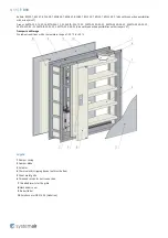
Page 6: ...3 S2 340TA 230 05 S2 340TA 024 05 S2 340CTA 024 05 S2 also with connection possibilities with acronyms ST Transport and Storage Dry indoor conditions with a temperature range of 20 C to 50 C Legend 1 Damper casing 2 Damper blade 3 Actuator 4 Thermoelectric tripping device with test button 5 Sheet metal grille 6 Threaded inserts for duct connection 7 Threaded inserts for the grille 8 Mechanism cove...

Page 7: ...response time Pass closure time Operational reliability Pass motorized cycle 10 200 cycles manual cycle 50 cycles modulated 20 200 cycles Fire resistance Resistivity depending on installation method and situation integrity E maintenance of the cross section under E mechanical stability under E cross section under E insulation I smoke leakage S Durability of response delay Pass sensing element resp...

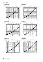
Page 8: ...ed 2000 3000 4000 m h 600 800 1000 1200 l s 10 20 30 40 Pa 25 dB A 30 dB A 35 dB A 40 dB A 45 dB A 50 dB A 55 dB A F B90 200x1000 00 Pressure drop sound power level A weighted 2000 3000 4000 5000 m h 600 800 1000 1200 1400 l s 10 20 30 40 Pa 25 dB A 30 dB A 35 dB A 40 dB A 45 dB A 50 dB A 55 dB A F B90 200x375 01 Pressure drop sound power level A weighted 600 800 1000 1200 1400 m h 200 300 l s 25 ...

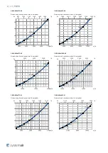
Page 9: ...0 1000 1200 m h 160 200 240 280 320 l s 25 50 75 Pa 25 dB A 30 dB A 35 dB A 40 dB A 45 dB A 50 dB A 55 dB A F B90 200x625 11 Pressure drop sound power level A weighted 1000 1500 2000 m h 300 400 500 l s 25 50 Pa 25 dB A 30 dB A 35 dB A 40 dB A 45 dB A 50 dB A 55 dB A F B90 200x875 11 Pressure drop sound power level A weighted 1500 2000 2500 3000 m h 400 500 600 700 800 l s 10 20 30 40 Pa 25 dB A 3...

Page 10: ... 1600 2000 2400 2800 3200 l s 10 20 Pa 25 dB A 30 dB A 35 dB A 40 dB A 45 dB A 50 dB A 55 dB A F B90 500x1000 00 Pressure drop sound power level A weighted 6000 8000 10000 12000 14000 m h 2000 3000 l s 4 8 12 16 20 Pa 25 dB A 30 dB A 35 dB A 40 dB A 45 dB A 50 dB A 55 dB A F B90 500x375 01 Pressure drop sound power level A weighted 1600 2000 2400 2800 3200 3600 m h 400 500 600 700 800 900 1000 l s...

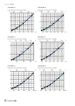
Page 11: ... 2000 2500 3000 m h 400 500 600 700 800 900 l s 25 50 Pa 25 dB A 30 dB A 35 dB A 40 dB A 45 dB A 50 dB A 55 dB A F B90 500x625 11 Pressure drop sound power level A weighted 3000 4000 5000 6000 m h 800 1000 1200 1400 1600 l s 10 20 30 Pa 25 dB A 30 dB A 35 dB A 40 dB A 45 dB A 50 dB A 55 dB A F B90 500x875 11 Pressure drop sound power level A weighted 4000 5000 6000 7000 8000 m h 1000 1500 2000 l s...

Page 12: ...ted 10000 15000 20000 m h 3000 4000 5000 l s 4 8 12 16 20 Pa 25 dB A 30 dB A 35 dB A 40 dB A 45 dB A 50 dB A 55 dB A F B90 800x1000 00 Pressure drop sound power level A weighted 10000 15000 20000 m h 3000 4000 5000 6000 l s 5 10 15 Pa 25 dB A 30 dB A 35 dB A 40 dB A 45 dB A 50 dB A 55 dB A F B90 800x375 01 Pressure drop sound power level A weighted 3000 4000 5000 6000 m h 800 1000 1200 1400 1600 l...

Page 13: ...d 3000 4000 5000 m h 800 1000 1200 1400 l s 25 50 Pa 25 dB A 30 dB A 35 dB A 40 dB A 45 dB A 50 dB A 55 dB A F B90 800x625 11 Pressure drop sound power level A weighted 4000 5000 6000 7000 8000 9000 m h 1500 2000 2500 l s 10 20 30 Pa 25 dB A 30 dB A 35 dB A 40 dB A 45 dB A 50 dB A 55 dB A F B90 800x875 11 Pressure drop sound power level A weighted 6000 8000 10000 12000 14000 m h 2000 3000 l s 4 8 ...

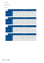
Page 14: ...14 69 F B90 Dimensions Free area ...

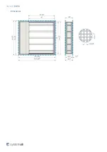
Page 15: ...15 69 F B90 Dimensions ...

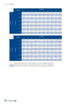
Page 16: ...16 69 F B90 Weights ...

Page 17: ...17 69 F B90 ...

Page 18: ...18 69 F B90 ...

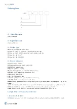
Page 19: ...imo Actuator modulated 0 10 V G230T 230V AC Gruner Actuator G24T 24V AC DC Gruner Actuator GST0 24V AC DC Supply comm unit 24V AC DC Gruner Actuator G24T SR 24V AC DC Gruner Actuator modulated 0 10 V BSD230T 230V AC Supply unit 24V AC DC Smoke detector 24V AC DC Belimo Actuator Available only with type 11 and 22 GSD230T AC DC 230 V Transformer 24V AC DC Smoke detector 24V AC DC Gruner Actuator Ava...

Page 20: ...d depicted instructions provided within User Manual closely perform damper inspection in accordance with User Manual check the damper s functionality as per the chapter Fire Damper Functionality Check before you install the fire damper This procedure prevents the installation of a damper that has been damaged during transportation or handling Information about installation maintenance and operatio...

Page 21: ...tructure The gap in the installation opening between the fire damper and the wall ceiling can be increased by up to 50 of the gap area or decreased to the smallest amount possible that still provides sufficient space for the installation of the seal When using non original grilles the gap between the damper blade in open position and the self standing grill mesh louvre must be at least 200 mm acco...

Page 22: ... s functional parts which might keep it from working properly The best way is to cover the functional parts during installation To prevent seepage of the filling material use of boards is recommended First let the plaster or mortar or concrete filling harden and then perform the next steps 4 After the filling hardens remove the duct support from inside the damper 5 If needed uncover and clean the ...

Page 23: ...23 69 F B90 Types 00 01 02 installed in the wall Max EI90S ...

Page 24: ...24 69 F B90 ...

Page 25: ...ted extension piece 7 Screw M6 20 25 mm maximum fixing torque is 4 5 Nm 8 Self tapping screw size 4 2 4 8 length 80 mm e g DIN 7981C DIN 7982C Y Cutting plane Y1 Cross section of Wet installation in flexible wall wall width is equal to 125 mm ended with grille Y2 Cross section of Wet installation in rigid wall wall width is equal to 125 mm ended with grille ...

Page 26: ...h is greater than 125 mm ended with grille Y5 Cross section of Wet installation in flexible wall wall width is equal to 125 mm Y6 Cross section of Wet installation in rigid wall wall width is equal to 125 mm Y7 Cross section of Wet installation in flexible wall wall width is greater than 125 mm Y8 Cross section of Wet installation in rigid wall wall width is greater than 125 mm ...

Page 27: ...ed with grille Y2 Cross section of Wet installation in rigid wall wall width is equal to 125 mm ended with grille Y3 Cross section of Wet installation in flexible wall wall width is greater than 125 mm ended with grille Y4 Cross section of Wet installation in rigid wall wall width is greater than 125 mm ended with grille Y5 Cross section of Wet installation in flexible wall wall width is equal to ...

Page 28: ...28 69 F B90 Types 11 22 installed in the wall Max EI90S EI120 ...

Page 29: ...29 69 F B90 ...

Page 30: ...equal to 125 mm ended with grille on both sides Y2 Cross section of Wet installation in rigid wall wall width is equal to 125 mm ended with grille on both sides Y3 Cross section of Wet installation in rigid wall wall width is greater than 125 mm ended with grille on both sides Y4 Cross section of Wet installation in flexible wall wall width is greater than 125 mm with connected extension piece and...

Page 31: ...mper widths greater than 600 mm it is recommended to use a duct support inside the damper during installation to avoid any damage caused to the damper housing by the weight of the filling 4 After inserting the damper into the opening fasten the damper using the suitable screws 8 as per the Handling of F B90 section Apply the same fire resistant coating 5 at least 2 mm thick and 10 mm wide to the o...

Page 32: ...32 69 F B90 Types 00 01 02 installed in the wall Max EI90S ...

Page 33: ...33 69 F B90 ...

Page 34: ...40 kg m3 4 Grille 5 Fire resistive coating Isover BSF ISOVER 6 Connected extension piece 7 Screw M6 20 25 mm maximum fixing torque is 4 5 Nm 8 Self tapping screw size 4 2 4 8 length 80 mm e g DIN 7981C DIN 7982C Y Cutting plane Y1 Cross section of Soft installation EI90S in flexible wall wall width is equal to 125 mm ended with grille ...

Page 35: ...oft installation EI90S in rigid wall wall width is greater than 125 mm ended with grille Y5 Cross section of Soft installation EI90S in flexible wall wall width is equal to 125 mm Y6 Cross section of Soft installation EI90S in rigid wall wall width is equal to 125 mm Y7 Cross section of Soft installation EI90S in flexible wall wall width is greater than 125 mm Y8 Cross section of Soft installation...

Page 36: ...ended with grille Y2 Cross section of Soft installation EI90S in rigid wall wall width is equal to 125 mm ended with grille Y3 Cross section of Soft installation EI90S in flexible wall wall width is greater than 125 mm ended with grille Y4 Cross section of Soft installation EI90S in rigid wall wall width is greater than 125 mm ended with grille Y5 Cross section of Soft installation EI90S in flexib...

Page 37: ...37 69 F B90 Types 11 22 installed in the wall Max EI90S EI120 ...

Page 38: ...38 69 F B90 ...

Page 39: ...e wall wall width is equal to 125 mm ended with grille on both sides Y2 Cross section of Soft installation in rigid wall wall width is equal to 125 mm ended with grille on both sides Y3 Cross section of Soft installation in rigid wall wall width is greater than 125 mm ended with grille on both sides Y4 Cross section of Soft installation in flexible wall wall width is greater than 125 mm with conne...

Page 40: ... For damper widths greater than 600 mm it is recommended to use a duct support inside the damper during installation to avoid any damage caused to the damper housing by the weight of the filling 4 After inserting the damper into the opening fasten the damper using the suitable screws 8 as per the Handling of F B90 section Apply the same fire resistant coating 5 at least 2 mm thick and 10 mm wide t...

Page 41: ...41 69 F B90 Types 00 01 02 installed in the wall Max EI90S ...

Page 42: ...in 140 kg m3 4 Grille 5 Fire resistive coating Isover BSF ISOVER 6 Connected extension piece 7 Screw M6 20 25 mm maximum fixing torque is 4 5 Nm 8 Self tapping screw size 4 2 4 8 length 80 mm e g DIN 7981C DIN 7982C Y Cutting plane Y1 Cross section of Fit installation in flexible wall wall width is equal to 125 mm ended with grille ...

Page 43: ...tion in flexible wall wall width is greater than 125 mm ended with grille Y3 Cross section of Fit installation in flexible wall wall width is equal to 125 mm Y4 Cross section of Fit installation in flexible wall wall width is greater than 125 mm ...

Page 44: ...44 69 F B90 Types 11 22 installed in the wall Max EI90S EI120 ...

Page 45: ... piece 7 Screw M6 20 25 mm maximum fixing torque is 4 5 Nm 8 Self tapping screw size 4 2 4 8 length 80 mm e g DIN 7981C DIN 7982C Y Cutting plane Y1 Cross section of Fit installation in flexible wall wall width is equal to 125 mm ended with grille on both sides Y2 Cross section of Fit installation in flexible wall wall width is greater than 125 mm with connected extension piece and ended with gril...

Page 46: ...46 69 F B90 Electrical connections NOTE TS_P_A Type of activation Power Supply Power consumption Actuator type ...

Page 47: ...47 69 F B90 ...

Page 48: ...48 69 F B90 ...

Page 49: ...49 69 F B90 ...

Page 50: ...r supply before working on any electrical equipment Allow only qualified electricians to work on the electrical system Microswitch Power Supply AC 125 250 V or DC 12 24 V Electric Parameters 3A NOTES Supply via safety isolation transformer Legend OPEN NO Blue cable colour NC Grey cable colour C Black cable colour CLOSED NO Blue cable colour NC Grey cable colour C Black cable colour ...

Page 51: ...ion Main power supply voltage A device that disconnects the pole conductors minimum contact gap 3 mm is required for isolation from the power supply Paralell connection of several actuators possible Power consumption must be observed Legend 1 Blue cable colour 2 Brown cable colour S1 Violet cable colour S2 Red cable colour S3 White cable colour S4 Orange cable colour S5 Pink cable colour S6 Grey c...

Page 52: ...ES Supply via safety isolation transformer Paralell connection of several actuators possible Power consumption must be observed Legend 1 Blue cable colour black for BF24 T 2 Red cable colour white for BF24 T S1 Violet cable colour white for BF24 T S2 Red cable colour white for BF24 T S3 White cable colour white for BF24 T S4 Orange cable colour white for BF24 T S5 Pink cable colour white for BF24 ...

Page 53: ... work on the electrical system Power consumption must be observed NOTES Connection scheme for standardly fitted BKN230 24 Legend 1 Jumper factory fitted Can be removed if necessary to be replaced by a thermoalectric trip the safety function will be triggered if terminals 1 and 2 are not linked 2 Jumper only used for commissioning purposes and without BKS24 3 2 wire conductor to BKS24 ...

Page 54: ... to work on the electrical system Power consumption must be observed NOTES Supply via safety isolation transformer Power consumption must be observed Legend 1 Blue cable colour 2 Brown cable colour 3 White cable colour 5 Orange cable colour S1 Violet cable colour S2 Red cable colour S3 White cable colour S4 Orange cable colour S5 Pink cable colour S6 Grey cable colour Tf Thermal fuse ...

Page 55: ...bserved NOTES Caution Main power supply voltage A device that disconnects the pole conductors minimum contact gap 3 mm is required for isolation from the power supply Paralell connection of several actuators possible Power consumption must be observed Legend 1 Blue cable colour 2 Brown cable colour S1 Violet cable colour S2 Red cable colour S3 White cable colour S4 Orange cable colour S5 Pink cabl...

Page 56: ...ork on the electrical system Power consumption must be observed NOTES Supply via safety isolation transformer Paralell connection of several actuators possible Power consumption must be observed Legend 1 Blue cable colour 2 Brown cable colour S1 Violet cable colour S2 Red cable colour S3 White cable colour S4 Orange cable colour S5 Pink cable colour S6 Grey cable colour Tf Thermal fuse ...

Page 57: ...on must be observed Legend A1 A2 Analog Application Digital input for manual override can be selected via bus as Normally Open standard open or Normally Closed standard closed Default Normally Open B Position of line termination 120 ohm if FS UFC24 2 is last Modbus or BACnet device in line C RS 485 Coms Modbus RTU or BACnet MS TP dip switch selectable D1 D2 Damper 1 Damper 2 Fire or smoke extracti...

Page 58: ...d to work on the electrical system Power consumption must be observed NOTES Supply via safety isolation transformer Power consumption must be observed Legend 1 Blue cable colour 2 Brown cable colour 3 Black cable colour 4 Grey cable colour S1 Violet cable colour S2 Red cable colour S3 White cable colour S4 Orange cable colour S5 Pink cable colour S6 Grey cable colour Tf Thermal fuse ...

Page 59: ... on any electrical equipment Only qualified electricians are allowed to work on the electrical system Power consumption must be observed NOTES Caution Main power supply voltage A device that disconnects the pole conductors minimum contact gap 3 mm is required for isolation from the power supply Legend 3 2 wire conductor to BKS24 ...

Page 60: ...k on the electrical system Power consumption must be observed NOTES Supply via safety isolation transformer Legend 1 Blue cable colour 2 Brown cable colour S1 Violet cable colour white for BF24 T S2 Red cable colour white for BF24 T S3 White cable colour white for BF24 T S4 Orange cable colour white for BF24 T S5 Pink cable colour white for BF24 T S6 Grey cable colour white for BF24 T Tf Thermal f...

Page 61: ...61 69 F B90 Operation manual ...

Page 62: ...62 69 F B90 ...

Page 63: ...63 69 F B90 ...

Page 64: ...64 69 F B90 ...

Page 65: ...e damper F B90 2 Connected sheet metal ductwork tested according to EN 1366 8 or EN 1366 9 3 Filling 4 Grille 8 Self tapping screw size 4 2 4 8 length 80 mm e g DIN 7981C DIN 7982C 9 Support brick metal delivery or wood stud not part of damper ...

Page 66: ...66 69 F B90 ...

Page 67: ...s and or filling as per the desired installation type 2b Carefully lift the fire damper with forklift crane 2c Place the fire damper in vertical position 2d Place the fire damper in the opening as a desired installation type A1 A2 A1 For Soft or FitFitted installation place the fire damper on filling 3 A2 For Wet installation place the fire damper on support 9 3a Loosen the screws on the mechanism...

Page 68: ...HERE IS AIR FLOWING IN THE DUCT SYSTEM Recommended Inspection Steps According to the EN 15 650 1 Damper identification 2 Date of inspection 3 Check the electrical connection of the activation mechanism where applicable 4 Check the damper for cleanliness and clean if necessary 5 Check the blade and sealing condition corrections enter in log if necessary 6 Check for proper closure of the fire damper...

Page 69: ...Systemair DESIGN 2020 10 07 HandBook_F_B90_en GB 1D2E1FF0 E010 11EA E8DD 8BBB7258CB9B ...

Reviews: