17/48 |
FDR-3G…OF
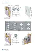
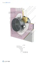
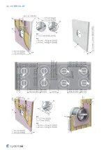
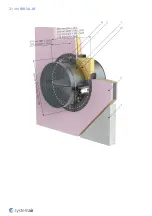
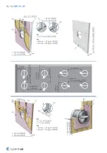
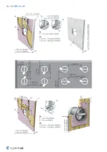
Installation rules
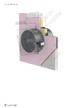
• The damper must not support any part of the surrounding construction or wall which could cause damage and
consequent damper failure.
• The damper driving mechanism can be placed on either side of the wall, however it needs to be placed so as to
ensure easy access during inspection. When the damper is fitted with smoke sensor, the damper must be rotated
so that the sensor is on highest posisition.
• According to the standard EN 1366-2, the distance between the fire damper bodies must be at least 200 mm. This
condition does not apply for tested distances. Therefore Wet and Soft installations are approved for smaller
distances under condition that the resulted resistivity is reduced to EI90S.
• The distance between the wall/ceiling and the fire damper must be at least 75 mm. This condition does not apply
for tested distances. Therefore Wet and Soft installations are approved for smaller distances under condition that
the resulted resistivity is reduced to EI90S.
• The fire damper must be installed into a fire partition structure in such a way that the damper blade in its closed
position is located inside this structure. A bendable hinge is provided on the damper body which represents a plane
where supporting construction begins.
• For each resistivity the minimum thickness of a its supporting construction cannot be decreased as per EN 1366-2
at least 200 mm from the installation opening.
• The gap in the installation opening between the fire damper and the wall/ceiling can be increased by up to 50% of
the gap area, or decreased to the smallest amount possible that still provides sufficient space for the installation of
the filling.
IN ACCORDANCE WITH EN 15650, EACH FIRE DAMPER MUST BE INSTALLED ACCORDING TO THE INSTALLATION
INSTRUCTIONS PROVIDED BY THE MANUFACTURER!
Summary of Contents for FDR-3G
Page 1: ...FDR 3G OF Overflow Fire Damper FDR 3G ...
Page 5: ...5 48 FDR 3G OF AM FD Activation Mechanisms CBR FD Cover Boards ...
Page 9: ...9 48 FDR 3G OF P15 Grid P16 Extended ductwork ...
Page 13: ...13 48 FDR 3G OF Dimensions Free area Dimensions Note 3 Inclusive bearing Overhangs Weights ...
Page 15: ...15 48 FDR 3G OF ø 250 DN ø630 Standardardly in position B On demand in position L T ...
Page 19: ...19 48 FDR 3G OF ...
Page 20: ...20 48 FDR 3G OF ...
Page 23: ...23 48 FDR 3G OF ...
Page 24: ...24 48 FDR 3G OF ...
Page 27: ...27 48 FDR 3G OF ...
Page 28: ...28 48 FDR 3G OF ...
Page 31: ...31 48 FDR 3G OF ...
Page 32: ...32 48 FDR 3G OF ...
Page 48: ...Systemair DESIGN 2020 10 23 HandBook_FDR_3G_OF_en GB 8519DCD0 0720 11EB DCA1 21ABDD8D93BC ...

