62/70 |
FDS...EX
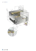
7 Multiple Damper Installation, EI90S
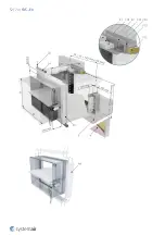
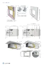
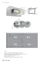
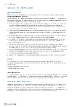
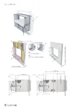
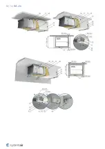
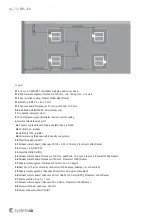
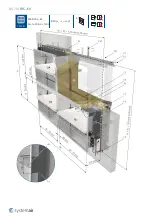
Installing a Set of FDS-EI90S Fire Dampers
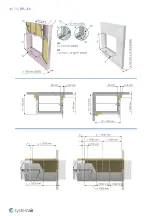
1. For a damper installation, prepare a square opening with the dimensions W1 and H1, the opening surfaces must be
even and cleaned off.
2. Determine the bottom level of the duct body crossing and insert L-profiles (F7) on both wall sides. While fixing with
screws (F8), perform a level check. Fill in the acquired area with mineral wool (F5) in the bottom and sides of the
opening. Before inserting into the opening, apply a fire-resistant layer/fire-resistive coating (F4) onto the contact
surfaces of the wool.
3. Before placing the dampers onto the profiles, prepare a slot cut out from the filled mineral wool. This slot cut out
will incorporate the protruding frame of the damper at the blade position. This slot cut must be performed in the
wool around all dampers.
4. Paint the insulation with fire-resistive layer (F4), as well as the contact surfaces with the damper and insert the
bottom damper FDS-1A.
5. Fix the bottom dampers through the L-profile using self-drilling screws (F8). with gaps of a max. of 200 mm.
6. Using fire-resistive coating (F4), glue mineral wool segments (F5) with a thickness of 80 mm to the FDS-1A
damper sides’ edging to the middle of the set. The dimensions of the mineral wool block need to correspond to the
entire area between the FDS-1A and FDS-1B damper so that the area is completely filled. Apply a fire-resistant
layer onto the external contact surfaces of the wool and the FDS-1A damper.
7. Place the second FDS-1B damper onto the L-profiles and press it against the first damper in such a way that the
dampers will be touching each other with flanges on both sides, and fasten them with suitable terminals. Attach
from the bottom through the L-profile using self-drilling screws (F8) with gaps of a max. of 200 mm. Secure the
dampers between each other with sheet metal belts (45) on both sides with screws (8) across the entire flange
contact surface. The maximum allowed gap between the screws is 200 mm.
8. On the top side of dampers FDS-1A and FDS-1B, forming a dividing line of the future second row FDS-2A and
FDS-2B, apply fire-resistive coating and place mineral wool with a thickness of 80 mm (F5). Using sheet metal belt
(45), create a backstop belt with a length of WL from one side of the installation and attach
it with screws (F8). If it is necessary to enhance the stability of the FDS-2A damper, fix it provisionally into the side
of the wall, until it is firmly embedded into the wall using an L-profile (F7).
9. Apply the same method used for the installation of FDS-2A also for the installation of the FDS-2B damper and face
the mechanism to the opposite side.
10. Any empty space that has remained between the dampers and the wall needs to be filled with wool and fire-
resistive coating. For this purpose, it is possible to dismount the mechanism from the dampers on which it is
hindering.
11. Fix the top dampers using L-profiles (F7) into the wall using screws (F1) and the profile with the damper using self-
drilling screws (F8) with maximum gaps of 200 mm.
12. All the L-profiles need to have consoles (F16) welded to them. Into a nominal dimension of the set WL = 1200 mm,
one console in the middle and for dimensions of WL > 1200 mm two consoles into 1/3 and 2/3 of the L-profile’s
length and screw them against the wall using screws (F1).
13. Make sure all touching flanges are covered with sheet metal belts (45) and fixed with screws (F8). The maximum
allowed gap between the screws is 200 mm.
14. Paint a fire-resistive coating (F4) on the insulation filling and damper body around the opening and between the
dampers. The minimal layer thickness is 2 mm. The width of the painted area is at least 100 mm.
15. Before the fire-resistive coating dries, remove the unwanted remnants of the coating.
16. If needed, uncover and clean the damper after installation and install the dismounted mechanisms.
17. Make sure the fixing screws are not interfering with the blade movement.
18. Check the damper functionality.
{1}
Summary of Contents for FDS-3G EX Series
Page 1: ...FDS EX Atex Fire Damper ...
Page 8: ...8 70 FDS EX Product parts ...
Page 27: ...27 70 FDS EX ...
Page 30: ...30 70 FDS EX ...
Page 31: ...31 70 FDS EX ...
Page 35: ...35 70 FDS EX ...
Page 36: ...36 70 FDS EX ...
Page 39: ...39 70 FDS EX ...
Page 40: ...40 70 FDS EX ...
Page 43: ...43 70 FDS EX 5 1 On Out FDS EI90S EX W 1600 H 1000 EI 90 ve i o S a b ...
Page 44: ...44 70 FDS EX ...
Page 48: ...48 70 FDS EX ...
Page 49: ...49 70 FDS EX ...
Page 52: ...52 70 FDS EX ...
Page 53: ...53 70 FDS EX ...
Page 57: ...57 70 FDS EX 5 4 On Out FDS 3G EX 100 100 1200 800 EI 60 ve i o S a b ...
Page 58: ...58 70 FDS EX ...
Page 59: ...59 70 FDS EX ...
Page 63: ...63 70 FDS EX 7 Multi FDS EI90S EX W 1600 H 1000 EI 90 ve i o S b ...
Page 70: ...Systemair DESIGN 2021 04 27 Handbook_FDS_EX_en GB ...

