background image

GB

Electrical connection |

11

8. Fill the system with the help of an external filling pump until the liquid flows out of the drain hose.

9. Close the filling valve X2.

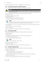
10.Open the stopcock X0. The valve X0 is open when the handgrip is parallel to the pipe.

11.With the help of the water system's pressure, set the system under a primary pressure of 1,5 bar. Use the filling

hose on filling valve X2 for that.

12.Pump the mixture through the system for about 30 minutes to remove air bubbles through the air vent.

13.Check the system pressure again and fill if necessary to rise the pressure.

14.Close the filling valve X1 and remove the filling hose.

15.Adjust the brine pump to the correct step.

16.Put the front door back.

Note:

Make sure to fill installation report with the liquid used.

5

Electrical connection

5.1

To do before the electrical connection

• Make sure that the electrical connection agrees with the product specification on the motor name plate.

• Make sure that the environment for electrical connection is clean and dry.

• Make sure that the wiring diagram that is included with the supply of the product agrees with the terminals in the

connection box.

5.2

To connect the product to the power supply

• Install a circuit breaker in the permanent electrical installation, with a contact opening of a minimum 3 mm at each

pole.

• Complete the electrical connection for the product.

Black/brown wire: L1, 230 V 1~, 50Hz

Blue wire: N neutral

Yellow/green wire: ground

5.3

To connect the product to the ventilation unit

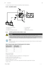
OAT

CB

DO

24V

230 V~ 

AI

GND

• Make sure that the outdoor temperature sensor (OAT)

is installed in the duct.

• Connect the temperature sensor wires (AI, GND) to

any free analog input and ground on the connection
board (CB) of the ventilation unit.

• Connect control signal wires (DO, 24V) to any free digi-

tal output and 24V on the connection board (CB) of the
ventilation unit.

• Install safety switches.

• Connect the power supply wires to 230 V~ output.

278349 | v01

Summary of Contents for GEO 300

Page 1: ...Document translated from English 278349 v01 GEO 300 GEO 500 GB User Manual 2 DE Bedienungsanleitung 24...

Page 2: ...yright Systemair UAB All rights reserved E OE Systemair UAB reserves the rights to alter their products without notice This also applies to products already ordered as long as it does not affect the p...

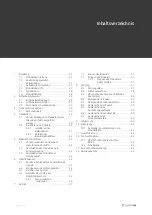
Page 3: ...6 Commissioning 12 6 1 To do before the commissioning 12 6 2 To configure the ventilation unit 12 6 3 To vent the system 12 6 4 To adjust the geothermal heat exchanger pump 12 6 4 1 Control modes and...

Page 4: ......

Page 5: ...e outdoor air temperature to make a pleasant indoor environment 1 2 Intended use The product is made for use with the comfort ventilation systems Any other use is considered an improper use and can le...

Page 6: ...ct causes in these conditions The product is incorrectly installed operated or maintained The product is repaired with parts that are not original spare parts from Systemair The product is damaged to...

Page 7: ...support if other servicing is necessary The product is not to be used by persons including children with reduced physical sensory or mental capabilities or lack of experience and knowledge unless they...

Page 8: ...tach the wall mounting bracket horizontally on the wall at least 100 mm distance from the ventilation unit Mind the dimensions of the product 590 x 390 x 720 mm 2 Hang the product 3 Connect the air du...

Page 9: ...galvanized pipes Pipes must be of suitable plastic If more than one pipe circuit is used the length of each pipe circuit should not exceed 100 m All pipe circuits must be the same length Make sure th...

Page 10: ...Concentration of more than 50 ethylene glycol will damage the system irreparably Note Fill the system with a ready to use ethylene glycol water mixture Please note the correct percentage of the ethyle...

Page 11: ...cal connection agrees with the product specification on the motor name plate Make sure that the environment for electrical connection is clean and dry Make sure that the wiring diagram that is include...

Page 12: ...o DO3 on the connection board then select DIGITAL OUT PUT 3 and select Step Controller Y4 Extra Controller from the output type list 6 Configure internal outdoor temperature sensor as extra controller...

Page 13: ...tart the manual restart or contact customer service Motor winding Winding is defective Flashes red Undervoltage or overvoltage Mains power supply is too low or high Measure the mains voltage and exami...

Page 14: ...onds to start the manual restart function Function lasts maximum 10 minutes Push and hold the control button for 5 seconds again to cancel Manual restart is used to unblock the pump for example after...

Page 15: ...product Maintenance task Each 3 months Each 6 months Each year Replace filters X Examine the pressure of the hydraulic circuit X Clean the product X Clean the condensate drain X 8 2 To replace filter...

Page 16: ...Close the filling valve X1 and remove the filling hose 8 Put the front door back 9 Connect the geothermal heat exchanger and ventilation unit to the power supply 8 4 To clean the product 1 Disconnect...

Page 17: ...emove the filling hose 9 Open the stopcocks X0 and X6 10 Put the front door back 11 Connect the geothermal heat exchanger and ventilation unit to the power supply 8 8 To replace the filling valve 1 Di...

Page 18: ...er is clogged Change the filter There is blockage in the air inlet or the duct system Remove the blockage There is unusual noise when the product starts or operates There is strain in the connections...

Page 19: ...dismounted without prior written permit of the manufacturer in the case of a warranty claim Spare parts are only covered by warranty if in stalled by an authorized installer The warranty expires if t...

Page 20: ...winter C Supply air temperature summer C 100 4 26 13 5 200 1 6 16 1 300 0 99 18 1 Table 5 Heating and cooling power GEO 500 m h Supply air temperature winter C Supply air temperature summer C 100 5 4...

Page 21: ...arts EN 60335 1 Household and similar electrical appliances Safety Part 1 General requirements EN 55014 1 Electromagnetic compatibility Requirements for household appliances electric tools and similar...

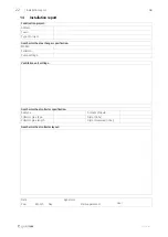
Page 22: ...exchanger specification Model Serial No Pump settings Ventilation unit settings Geothermal heat collector specification Soil type Amount of liquid Collector pipe type Glycol in Collector pipe length G...

Page 23: ...2783492 v01...

Page 24: ...ystemair UAB Alle Rechte vorbehalten E OE Systemair UAB beh lt sich das Recht vor ihre Produkte ohne vorherige Ank ndigung zu ndern Dies gilt auch f r bereits bestellte Produkte sofern die vorher vere...

Page 25: ...des Produkts am L ftungsger t 34 6 Inbetriebnahme 34 6 1 Vor der Inbetriebnahme auszuf hrende Schritte 34 6 2 Konfigurieren des L ftungsger ts 34 6 3 Entl ften des Systems 35 6 4 Einstellen der Pumpe...

Page 26: ......

Page 27: ...2 Bestimmungsgem e Verwendung Das Produkt ist zur Verwendung mit den Komfortl ftungssystemen ausgelegt Jegliche andere Form der Verwendung gilt als unsachgem er Gebrauch und kann zu Ger tesch den ode...

Page 28: ...olgenden Bedingungen verursacht werden Das Produkt wurde fehlerhaft montiert betrieben oder gewartet Das Produkt wird mit Ersatzteilen repariert die keine Originalteile von Systemair sind Das Produkt...

Page 29: ...icherheitsvorrichtungen und pers nliche Schutzausr stung Nehmen Sie Wartungsarbeiten nur gem diesem Handbuch vor Wenden Sie sich an den technischen Kundendienst von Systemair falls andere Reparaturarb...

Page 30: ...en Sie sicher dass der Montageort vor Frost gesch tzt ist Die Fl ssigkeit im System darf nicht einfrieren Stellen Sie sicher dass der Installationsort ausreichend Tragekapazit t f r das Gewicht des Pr...

Page 31: ...m Rohrdurchmesser Zirkulationspumpen stufe Gesch tzter Solegehalt Liter Trockener Sand 500 DN32 1 280 Feuchter Sand 250 DN32 1 145 Trockener Lehm 200 DN32 1 130 Feuchter Lehm 170 DN32 1 100 4 2 1 2 In...

Page 32: ...ng 1 2 3 4 5 6 1 Erdw rmetauscher 2 Ventilatoreinheit 3 Anschluss des Kondensatablaufs 4 Entl ftungsventil 5 Ausgleichsventil 6 Erdw rmekollektor 4 2 2 Bef llen des Erdw rmekollektors Warnung Nur ein...

Page 33: ...pen Sie das Gemisch ungef hr 30 Minuten lang durch das System um die Luftblasen ber die Entl ftungsklappe zu entfernen 13 berpr fen Sie erneut den Druck im System und bef llen Sie es bei Bedarf erneut...

Page 34: ...uschers wenn das L f tungsger t korrekt konfiguriert wurde Konfiguration 1 Stellen Sie sicher dass das L ftungsger t eingeschaltet ist 2 Wechseln Sie zu Service Konfiguration Systeminformationen 3 Geb...

Page 35: ...mefunktion besteht Zum Einstellen der Pumpe muss der Erdw rmetauscher eingeschaltet sein Falls erforderlich k nnen Sie die Einstellungen am L ftungsger t vor bergehend ndern um den Bedarf der K hl ode...

Page 36: ...ung Stellen Sie sicher dass die Menge des Gemischs und der Systemdruck korrekt sind Stellen Sie sicher dass die Werte der Umgebungsbedingungen im zul ssigen Bereich liegen Trockenlauf Luft in der Pump...

Page 37: ...die Pum pe aus Die Pumpe l uft mit den Werkseinstellungen wenn sie wieder eingeschaltet wird 7 Betrieb Lesen Sie sich das Handbuch des L ftungsger ts durch um weitere Informationen zur Temperaturregel...

Page 38: ...ichtung von rechts nach links verl uft 4 Setzen Sie den neuen Filter ein 5 Bringen Sie die Vordert r wieder an 6 Schlie en Sie den Erdw rmetauscher und das L ftungsger t an die Stromversorgung an 8 3...

Page 39: ...er L sungsmittel 6 Setzen Sie nach Abschluss aller Arbeiten den Filter ein 7 Bringen Sie die Vordert r wieder an 8 Schlie en Sie den Erdw rmetauscher und das L ftungsger t an die Stromversorgung an 8...

Page 40: ...fnen Sie das entsprechende F llventil langsam bis der gesamte Druck abgelassen ist 6 Tauschen Sie das F llventil aus 7 Bef llen Sie das System auf einen normalen Druck von 1 5 bar Siehe Kapitel 8 3 8...

Page 41: ...Produkts tritt ein ungew hnliches Ger usch auf Die Verbindungselemente des Kanalsystems sind verspannt L sen Sie die Verbindungselemente richten Sie die Teile des Kanalsystems korrekt aus und ziehen...

Page 42: ...im Fall eines Garantieanspruchs nicht demontiert werden Ersatzteile fallen nur dann unter die Garantie wenn sie von einem autorisierten Monteur installiert werden Die Garantie erlischt in folgenden F...

Page 43: ...mperatur Winter C Zulufttemperatur Sommer C 100 4 26 13 5 200 1 6 16 1 300 0 99 18 1 Tabelle 5 Heiz und K hlleistung GEO 500 m h Zulufttemperatur Winter C Zulufttemperatur Sommer C 100 5 4 12 5 150 4...

Page 44: ...he Ger te f r den Hausgebrauch und hnliche Zwecke Sicherheit Teil 1 Allgemeine Anforderungen EN 55014 1 Elektromagnetische Kompatibilit t Anforderungen an Haushaltsger te Elektrowerkzeuge und hnliche...

Page 45: ...ell Seriennr Pumpeneinstellungen Einstellungen des L ftungsger ts Technische Daten des Erdw rmekollektors Bodentyp Fl ssigkeitsmenge Typ des Kollektorrohrs Glykol in L nge des Kollektorrohrs Gemessene...

Page 46: ...GEO 300 GEO 500 278349 2021 10 20 v01 www systemair com...

Reviews: