Systemair NOVA drive 370
|
13
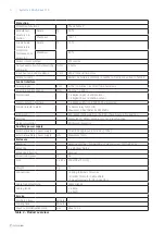
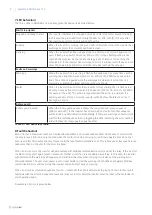
Error
Blinks
Retries
Flag bit
Value in AlarmLog
Rotary guard
Always on
3
(no auto reset)
8
9
Overcurrent stop
1
2
0
1
Overvoltage
2
2
1
2
Undervoltage
3
1
2
3
Hardware error (gate kill)
4
1
3
4
Modbus communication
5
Unlimited
15
15
Overheating stop
6
1
4
5
Backend communication
7
0
5
6
CRC error
8
0
7
8
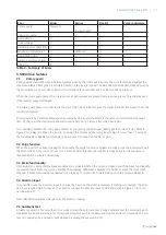
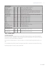
Table 9 – Summary of errors
9 NOVA drive features
9.1
Rotary guard
Rotary guards counts the time in between pulses given by the rotary guard sensor. The time is compared against the
maximum allowed time which is calculated based on the inverter speed. The time allowed at maximum speed given by
the dip switches is 12 seconds to permit 2 full rotations (2x5 seconds) and 2 extra seconds of tolerance.
When the rotary guard passes the rotary sensor an LED sequence is played (red-green-red-green). This will play even
if the inverter output is stopped.
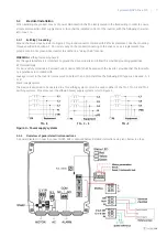
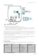
The rotary guard sensor is connected to the Uout (10V), 0V and RUN, to give the signal to NOVA. See Figure 10 for the
connection diagram.
Rotary guard is by default enabled and will eventually stop (coast) the Motor if the pulse is not detected for enough
time. At this point the inverter will attempt to start again up to 3 times, after which it will stop.
It is possible to disable the rotary guard feature by connecting the RUN input (Rotary guard) to Uout (10V). Refer to
Figure 9 for a diagram. When the inverter is running the motor and the rotary input is high for more than 10 seconds
the functionality is disabled. At this point a power reset is needed, to enable it again.
9.2 Purge function
When the inverter has been stopped for 30 minutes the purge function is activated. During purge the inverter will start
the motor and set it to run at 10 rpm for 12 seconds. After this time the inverter is stopped again. The sequence is
repeated after 30 minutes of inactivity.
9.3 Brake functionality
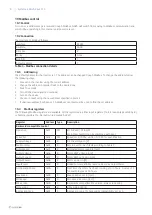
If dip switch 4 is set to ON the brake functionality is activated. When the motor is stopped and if the brake functionality
is activated it will brake the rotor by shorting the windings. With brake activated it is harder to move the rotor, when
stopped. If brake functionality is activated it can take up to 10 seconds to start braking once the motor is stopped.
9.4 Direction input
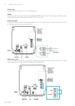
It is possible to use the direction input to change the direction the motor is spinning. If nothing is connected, the direc-
tion input is pulled high. To reverse the direction connect the direction input to 0V. Refer to (B) in Figure 11 for a con-
nection diagram.
Note that direction will not change once the motor is running.
9.5 Automatic test
Activate dip switch 5 for more than 10 seconds to start the automatic test. During automatic test the motor will go to
maximum speed and wait there for 10 seconds. After this it will ramp down and stop for another 10 seconds. The pro-
cess is repeated again and again, until stopped by setting the dip switch 5 off.


