PKIR, PKIS
| PP-28_201612 | 15 / 48
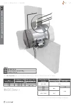
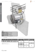
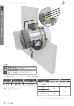
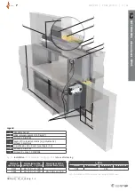
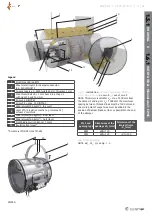
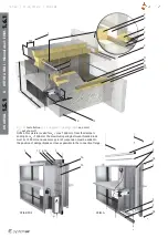
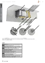
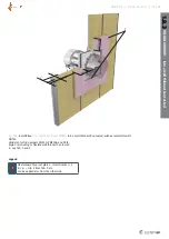
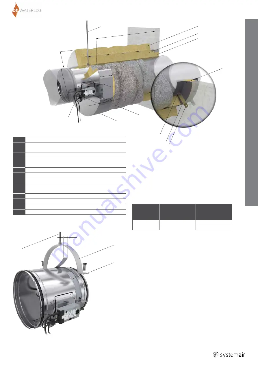
Fig. 14:
Installation
of a round fire damper PKIR3G
100 ≤
DN
≤ 630 mm
on a wall
and
out of a wall
NOTE: This picture is valid for
L
D
= max. 1500 mm from
the damper’s ending. For
L
D
> 1500 mm the maximum
spacing between threaded rods must be 1500 mm and
one more point of suspension must be added in the
position of damper blade as close as possible to the end
of the damper.
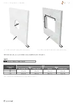
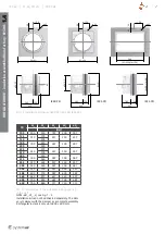
Wall and
opening type
Dimensions of the
openings ø
D
1
(mm)
Dimensions of the
internal frame
□
D
2
(mm)
RRW
ø
DN
+120
-
FRW
ø
DN
+120
□
DN
+120
Tab. 20: Wall opening
NOTE:
øD
1
, W
1
, H
1
see Fig. 1 - 4
1
Steel threaded rod M12
2
Sheet metal ringlet for damper suspension
(e.g. MP-MX/HILTI)
3
Ceramic tape (e.g. A-KERA) width 40 mm, thickness 2 mm
4
Sheet metal belt 40
×
2 mm bent into a shape L
with sides 35 and 160 mm
5
Screw 5,5 DIN7981
6
Screw 3,9 × max. 13 DIN7504
7
Mineral wool (66 kg/m
3
) - in a wall
8
Layer of fire resistive mastic (e.g. Intumex AC)
at least 2 mm thick
9
Mineral wool (66 kg/m
3
) - inner layer
10
Mineral wool (66 kg/m
3
) - outer layer
11
Steel binding wire thickness 1,6 mm
12
Insulation front cover*
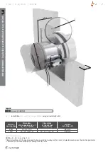
Legend
* Accessory IPOR-PKI (see TPI-28)
1.5.1
ON
A W
ALL
&
1.6.1
OUT
OF
A W
ALL
- Miner
al
w
ool - EI90S
8
9
7
12
11
18
0
150
6
4
5
1
10
6
ø
DN
170
40
15
5
L
D
2
3
40
PKIR3G
1


