PKIR, PKIS
| PP-28_201612 | 19 / 48
1.5.2
ON
A W
ALL
&
1.6.2
OUT
OF
A W
ALL
- Miner
al
w
ool - EI60S
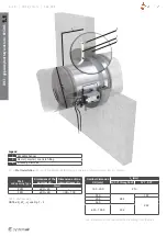
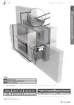
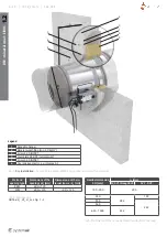
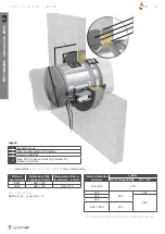
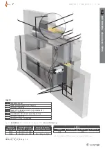
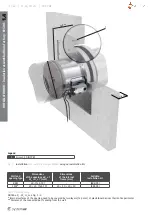
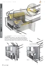
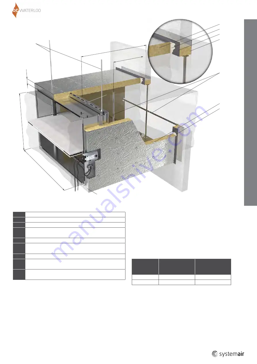
Fig. 15ba:
Installation
of a rectangular fire damper
PKIS3G
on a wall
and
out of a wall
- fire resistivity EI60S
NOTES: This picture is valid for
L
D
= max. 1500 mm from
the damper’s ending. For
L
D
> 1500 mm the maximum
spacing between threaded rods must be max. 1500 mm
and one more point of suspension must be added as
close as possible to the connection flange.
L
D
80
H
W
6
5
4
3
1
2
8
L
S
5
7
9
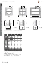
Wall and
opening type
Dimensions
of the openings
W
1
×
H
1
(mm)
Dimensions
of the internal
frame (mm)
RSW
W
+ 120 ×
H
+ 120
-
FSW
W
+ 120 ×
H
+ 120
W
+ 120 ×
H
+ 120
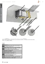
1
Steel threaded rod M10
2
U-profile (e.g. MQ31/HILTI) Top & Bottom
3
Mineral wool (66 kg/m
3
)
4
Layer of fire resistive mastic (e.g. ISOVER Protect BSF)
on both side at least 2 mm thick
5
Layer of fire resistive glue (e.g. ISOVER Protect BSK)
6
Mineral wool th. 80 mm (min. 66 kg/m
3
;
e.g. ISOVER Ultimate U-Protect Slab 4.0 Alu1)
7
Welding pin – length 80 mm *
8
Stiffening rods: horizontal for
W
> 600 mm;
vertical for
H
> 400 mm. **
9
Aluminium tape around the front side
and on places uncovered with aluminium foil
Legend
Tab. 22b: Wall opening
NOTE:
øD
1
, W
1
, H
1
see Fig. 1 - 4
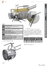
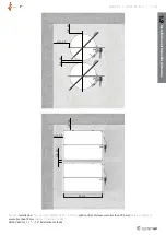
* Top without welding pins, side 20 pins/m
2
,
bottom 20 pins/m
2
; distance between pins max. 260 mm,
distance of the pin from the edge 80 mm
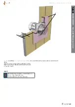
** Along the insulated duct - the first stiffening rod is placed
inside the wall. Each subsequent stiffening rod must be placed
with an
L
S
distance = max. 1000 mm. The last stiffening rod must
be placed 1000 mm from the fire damper flange at most. If the
fire damper flange is closer to the wall than the overhang of the
open blade (
R
2
; see Tab. In TechSpec_TPI-28...), then move the
first stiffening rod to the right so that the distance between the
stiffening rod and the fire damper flange is
R
2
+ 50 mm.


