42 / 48 | PP-28_201612 | PKIR, PKIS
1.8 Installations into a wall thinner than tested
1.8.1
INSTALLATION into a wall thinner than tested
-
WET
(Fig. 18a)
1.8.2
INSTALLATION into a wall thinner than tested
-
SOFT CROSSING
(Fig. 18b)
1.8.3
INSTALLATION into a wall thinner than tested
-
INSTALLATION KIT
(Fig. 18c)
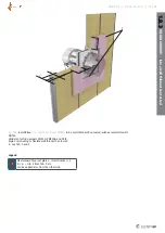
Installation into a thinner wall is allowed under the condition
that additional layer/layers of fire protective board are fixed to
the surface of the wall in order to achieve the same length of
damper penetration seal as was tested. The minimum width of
added boards around the damper is 200 mm. Also the alternative
thinner wall should be classified in accordance with EN 13501-
2:2007 + A1: 2009 for fire resistance required for product appli-
cation. For a protruding wall the additional layers must be fixed
on the steel supporting construction of the wall.
2 Operation Manual
After installation it is necessary to adjust the damper into its
operating position – open the fire damper, close the evacuation
damper.
2.1 Servomotor-operated activation mechanism
Connect the electric driving mechanism to the relevant electric
power supply (Fig. 23, 24, 26, 27, 28, 31). The electromotor is
activated and adjusts the damper into its operating position.
2.2 Manually operated fire damper activating me
-
chanism
Turn and detent the crank into the „OPEN“ position (Fig. 29 and
30). The damper blade opens and if the damper is connected as
per the damper connection (Fig. 25), the control system signals
the damper blade’s open position.
2.3 Manually operated fire damper activating
mechanism with an electromagnet
The process is the same as in 2.2 and in addition it is necessary
to connect the electromagnet to the control system, which will
control the electromagnet in case of the fire damper activation
from the control center (Fig. 25, 29, 30 and Tab. 26 and 27).
3 Fire Damper Functionality Check
3.1 Manual
•
Open the damper – turn the crank using a four-square wrench
(damper dimensions
W
≤ 1200 and
H
≤ 800 mm) / turn the
crank into the “OPEN“ position and detent (damper dimensions
W
> 1200 and/or
H
> 800 mm) – the crank needs to remain
in the “OPEN“ position, the microswitch for the open position
indication must be braced (if installed).
•
Close the damper – release the mechanism using the crank
(damper dimensions
W
≤ 1200 and
H
≤ 800 mm) / pulling
the locking pin (damper dimensions
W
> 1200 and/or
H
>
800 mm) – the crank needs to adjust itself into the “CLOSED“
position and remain locked in this position, the microswitch for
the closed position indication must be braced (if installed).
•
Open the damper – turn the crank using a four-square wrench
(damper dimensions
W
≤ 1200 and
H
≤ 800 mm) / turn the
crank into the “OPEN“ position and detent (damper dimensions
W
> 1200 and/or
H
> 800 mm) – the crank needs to remain
in the “OPEN“ position, the microswitch for the open position
indication must be braced (if installed).
3.2 Servomotor operated activation mechanism
•
The fire damper must open / the evacuation damper must
close automatically after the servo circuit closes – the arrow on
the servo axis must show position 0°.
•
Press the control switch on the thermal fuse (Fig. 22) and hold it
until the fire damper is fully closed / evacuation damper is fully
open – the arrow on the servo axis must show position 90°.
•
Release the control switch on the thermal fuse. The fire
damper must become fully open / evacuation damper must be
fully closed – the arrow on the servo axis must show position
0° - which is the operating position.
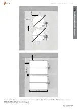
1.9 Installations with smaller distances
(Fig. 19a, b)
The distance between individual fire dampers can be reduced
to 60 mm, measured from surface to surface of housing and
distance between the surface of damper installed in the duct and
the adjacent supporting construction (wall/floor) can be reduced
to 40 mm, provided that the fire resistance classification will be
reduced as follows: EI 90 (ve i ↔ o) S


