background image

PKIR-E60S & EKIR-E60S


|    PP-87_201701    |    3 / 8

1 Installation manual

• 

All connecting ducts to the fire damper must be supported or 

suspended in such a way that the duct weight would not lean 

on the damper. Furthermore the damper should not bear any 

weight from the above or surrounding construction; this can 

result in distortion of the casing and ultimately malfunctioning 

of the fire damper.

• 

The damper actuator can be located on any side of the fire 

resistant wall, however it must be positioned in such a way 

that there is easy access provided for inspection or service.

• 

Spacing between the dampers must be a minimum of 200 

mm.

• 

Space between the wall/ceiling and the damper must be at 

least 75 mm.

• 

All dampers can be installed with the blade in a horizontal or 

vertical position.

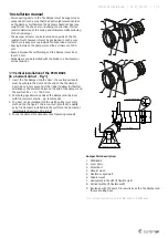
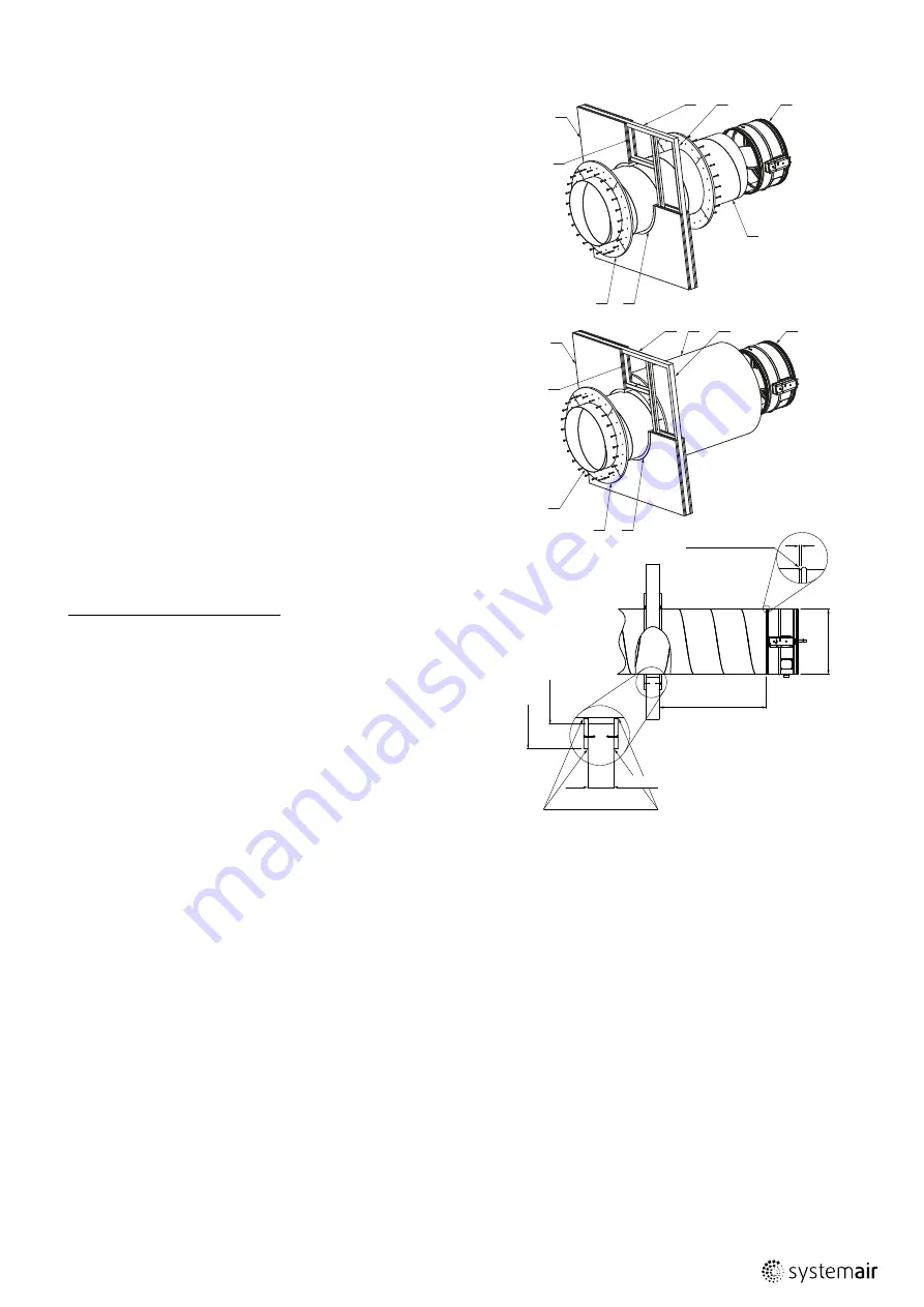
Fig.1: Vertical installation of the PKIR-E60S and EKIR-E60S

3

1

7

8

4

2

5

6

1.1 Vertical installation of the PKIR-EI60S  

(in a horizontal duct – Fig.1)

1.  Insert the fire damper into the duct - the sealing spiro safe 

must be wholy in the duct and the end of the fire damper 

has to be ca 5 mm away from the ridge (to allow for thermal 

dilatations). The distance between the end of the damper and 

the wall can be 

L

 = 0 – 1500 mm. 

2.  Seal both gaps between ends of the damper and the duct 

with fire resistant mastic – e.g. Intumex AN. 

3.  The duct can be installed into the wall by either wet or dry 

method (on the figure 1 there is only dry method), equally 

as by fire dampers installed into the wall (see the document 

InstalMaintenOperInstr_PP-28_EN)

4.  Check the damper functionality. (See Operating manual)

Damper Parts Description:

1.  PKIR-E60S

2.  Cover plate

3.  Metal duct

4.  Mineral wool

5.  Flexible or rigid wall

6.  Mineral wool

7.  Horizontal profile UW (if flexible wall)

8.  Vertical profile (if flexible wall)

9.  Insulation with the same fire resistivity as the fire damper and 

the wall ceiling have

125 min.

5

to seal (Intumex AN)

ØD

0-1500

mastic (Intumex AN)

ØD+60

ØD+X

2

5

3

4

1

6

8

7

9

Summary of Contents for PKIR-E60S

Page 1: ...IR E60S and EKIR E60S Round Fire and Evacuation Damper INSTALLATION OPERATION AND MAINTENANCE INSTRUCTIONS EACH FIRE EVACUATION DAMPER MUST BE INSTALLED ACCORDING TO THIS INSTALLATION MANUAL 1396 CPD 0069 ...

Page 2: ...driving mechanism as standard They are intended for installation in places which are protected against weather disruptions in the ducts distributing air without any mechanical or chemical contamination in the following operating conditions Maximum air flow velocity 12 m s Temperature within the range 10 up to 60 C From the noise perspective all Systemair dampers are passive Increased noise can onl...

Page 3: ...nstallation of the PKIR EI60S in a horizontal duct Fig 1 1 Insert the fire damper into the duct the sealing spiro safe must be wholy in the duct and the end of the fire damper has to be ca 5 mm away from the ridge to allow for thermal dilatations The distance between the end of the damper and the wall can be L 0 1500 mm 2 Seal both gaps between ends of the damper and the duct with fire resistant m...

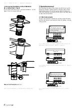
Page 4: ...Fig 1 Fig 2 Horizontal installation of the PKIR E60S and EKIR E60S 4 3 2 1 ØD 60 ØD ØD 100 ØD X 0 1500 5 mastic Intumex AN to seal Intumex AN mastic Intumex AN 1 2 Horizontal installation of the PKIR E60S in a vertical duct Fig 2 It is the same procedure as in 1 1 Vertical installation on the figure 2 there is only dry method Note Caution Main power supply voltage A device that disconnects the pol...

Page 5: ...his depends on operation temperature The position of the blade is possible to check visually through the inspection lid or the blade position is signalized by the control system which the damper is connected to Damper must close open also at any interruption of electricity supply when the damper blade is moved by the energy of the actuator s return spring 5 Warranty Conditions For warranty conditi...

Page 6: ...te of the following inspection after deficiencies elimination Inspection technician s signature Periodic damper inspections at least once in 12 months Date Description of found defects and date of the following inspection after deficiencies elimination Inspection technician s signature Operation Journal ...

Page 7: ...R E60S PP 87_201701 7 8 Periodic damper inspections at least once in 12 months Date Description of found defects and date of the following inspection after deficiencies elimination Inspection technician s signature ...

Page 8: ... resistance maintenance of the cross section under E integrity E E60 ve ho i o S insulation I smoke leakage S mechanical stability under E cross section under E Durability of response delay sensing element response temperature and load bearing capacity Pass Durability of operational reliability open and closing cycle Pass Damper Identification Building object Emplacement Room no Position no Identi...

Reviews: