4 / 8 | PP-87_201701 | PKIR-E60S & EKIR-E60S
2 Operation manual
After installing the damper the actuator needs to be set up into
emergency position, meaning that the fire/evacuation damper
blade will open/close. The control system which the damper is
connected to signals (according to the damper connection) opens
or closes the damper blade.
2.1 Electrical actuator
Connect the electrical actuator to power (see wiring schemes)
and the electromotor is activated and puts the damper into ope-
rating position.
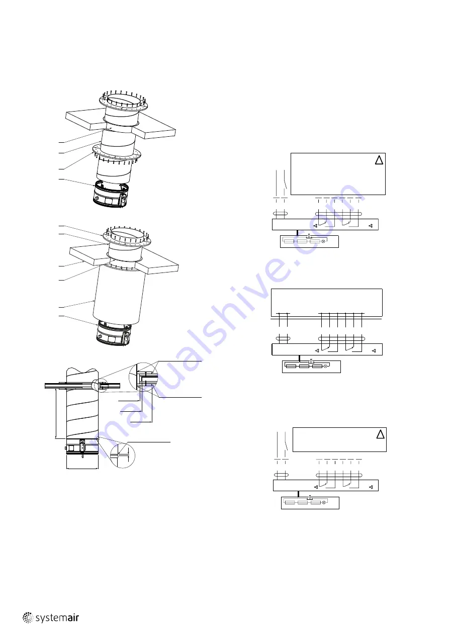
Fig. 3: Wiring scheme of actuators BELIMO BLF230-T (BFL and
BFN instead of BLF), BFL230-T, BFN230-T, BF230-T
Fig. 4: Wiring scheme of actuators BELIMO BFL24-T-ST, BFN24-T-
ST, BF24-T-ST
Fig. 5: Wiring scheme of actuator BELIMO BFL24-T, BFN24-T,
BF24-T
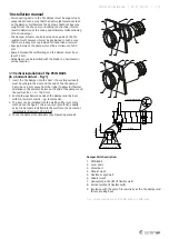
Damper Parts Description:
see Fig. 1
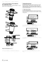
Fig. 2: Horizontal installation of the PKIR-E60S and EKIR-E60S
4
3
2
1
ØD+60
ØD
ØD+100
ØD+X
0-1500
5
mastic (Intumex AN)
to seal (Intumex AN)
mastic (Intumex AN)
1.2 Horizontal installation of the PKIR-E60S
(in a vertical duct – Fig.2)
It is the same procedure as in 1.1 Vertical installation... (on the
figure 2 there is only dry method)
Note
• Caution: Main power supply voltage!
• A device that disconnects the pole conductors
(minimum contact gap 3 mm) is required for iso
-
lation from the power supply.
• Parallel connection of several actuators possible.
Power consumption must be observed!
!
S1 S2 S3 S4 S5 S6
<5°
<80°
2
1
N L1
BAE or BAT
Tf1
Tf2
Tf3 LED
Connecting lead with plugs for linking to the communication
and power units
S1 S2 S3 S4 S5 S6
<5°
<80°
2
1
T
~
BAE or BAT
Tf1
Tf2
Tf3 LED
Note
• Supply via safety isolation transformer
• Parallel connection of several actuators possible.
• Power consumption must be observed!
!
S1 S2 S3 S4 S5 S6
<5°
<80°
2
1
– +
T
~
BAE or BAT
Tf1
Tf2
Tf3 LED
1
2
3
4
5
9


