PKIR-E60S & EKIR-E60S
| PP-87_201701 | 5 / 8
Operational conditions
The actuator keeps the fire dampers in operation and in safe
status during their whole period of service. It is not permitted
to change or modify the dampers and any damper parts cannot
be removed without the manufacturer’s permission. The opera-
tor regularly checks the dampers according to instructions and
norms given in the country.
If not stated otherwise the operator does the damper check once
every 12 months. Damper checking is to be done by an autho-
rized person. The damper status determined during the check is
noted into the operation diary with the date of the check, name,
last name and signature of the person that has done the check. If
any inadequacies are determined it is necessary to note a propo-
sal for their elimination into the operation diary.
During a visual check visible damages to the damper parts are
also to be checked. From the outer side of the damper check the
damper casing and actuator. During a visual check from the inner
part of the damper, the inspection lid is dismounted and the
sealing is checked together with the intumescent material. Check
the damper inner casing, thermo-electrical release device, all the
sealings inside the damper, damper blade and also the correct-
ness of the damper blade closure (when it is at the end stop in
closed position). The damper blade must be open in operation
mode.
Do not open the inspection lid in the event of airflow in
the ductwork!
3 Fire Damper Functionality Check
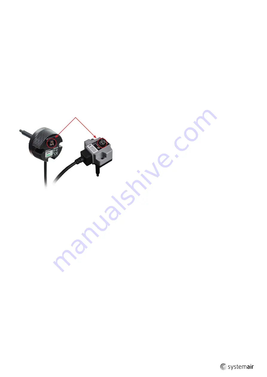
The damper function is checked when the switch on the ther-
mo-electrical release device is pressed and held as shown in Fig.
6. With the switch you simulate a failure of the thermal electrical
release device. It is necessary to hold the switch in ON mode
during the whole damper function check. The actuator puts
the damper into emergency position – it closes/opens the fire/
evacuation damper blade with the energy of return spring of
the actuator. The damper should close/open within about 20-30
seconds (this depends on operation temperature). The position
of the blade is possible to check visually through the inspection
lid or the blade position is signalized by the control system which
the damper is connected to.
Damper must close/open also at any interruption of electricity
supply when the damper blade is moved by the energy of the
actuator’s return spring.
5 Warranty Conditions
For warranty conditions ask please our Systemair colleagues in
your country.
Before you can install the fire damper, it‘s functionality must be
tested as per chapter 3 (Fire Damper Functionality Check).
DO NOT INSTALL NON-FUNCTIONING FIRE DAMPERS!
Changes of fire damper functionality, caused by transport or
installation, aren‘t reclaimable after installation (deformations,
damages, mechanical damage of the sealing material, foreign
objects which can constrain the blade movement, wrong hand-
ling of the activating mechanism etc.)
Before you can connect the fire damper into the ductwork, the
fire damper functionality must be checked again (according to
chapter 3, in Fire Damper Functionality Check).
4 Damper inspection
During the check the damper should be in operational mode,
meaning that during the visual check the fire/evacuation damper
blade is open/closed. Correct functioning of the actuator release
is checked by holding the switch on the thermo-electrical release
device. Closing/opening of the damper is provided by the spring.
After the function check put the damper into operation mode by
releasing the switch on the thermo-electrical release device.
Recommended checks according to the EN 15 650 regulation:
1. date of inspection
2. check of the end switch’s connection for damage, if appli-
cable
3. check for damper cleanliness and clean if needed
4. check the blades and sealing, correction and record if
needed
5. check the fire damper’s safe closure – for details please see
the previous section
6. check if the damper moves while in its open and closed
position, correct and record if needed
7. check the end switch indicating the open and closed positi-
on, correct and record if needed
8. check if the damper is in its standard position.
Switch
Fig. 6: Electro-thermal fuse - control switch
BAE
actuator BF
BAT
actuator BFL and BFN


