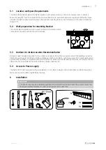
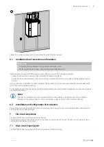
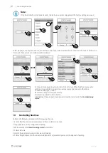
background image

Before Starting the System |

11

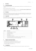
Fig. 5 External connection box and board

Position

Description

1

Connection to the main circuit board

2

Connection for external control panel (HMI) or Internet access module (IAM)

3

Modbus RS485 connection

AI6–7

Freely configurable Analog input. None/Input type selection in HMI.

DO1–4

Freely configurable digital output.
DO2 default configuration: Outdoor-/Exhaust Air Damper
DO3 default configuration: Activate Cooling
DO4 default configuration: Sum Alarm

AO3–5

Freely configurable analog output. Actuator type 0–10V, 10–0V, 2–10V, 10–2V.
AO3 default configuration: Heating (only for VTC 200/300/500/700, VTR 100/700 type models).
AO4 default configuration: Cooling

UI1–5

Freely configurable universal input. Can be set as analog input (0–10 V) or a digital input (24 V).
UI1 default configuration: Pressure guard
UI2 default configuration: Cooker hood
UI3 default configuration: Fire alarm
UI4 default configuration: Refresh

24V

Maximum current 200mA at 24VDC +-10%.

8

Before Starting the System

When the installation is completed, check that:

• The unit is installed in accordance with the instructions

• Outdoor and exhaust air dampers and silencers are installed and that the duct system is correctly connected to the

unit

• All ducts are sufficiently insulated and installed according to local rules and regulations

• Outdoor air intake is positioned with sufficient distance to pollution sources (kitchen ventilator exhaust, central vac-

uum system exhaust or similar)

• All external equipment is connected

• The unit is correctly wired

9

Commissioning

Follow the first startup instructions and fill in the

Commissioning record

as you go through the settings.

The Startup Wizard cannot be skipped.

254496 | v01

Summary of Contents for SAVE VTR 250/B

Page 1: ...Document in original language 254496 v01 SAVE VTR 250 B Installation instructions GB...

Page 2: ...s the rights to alter their products without notice This also applies to products already ordered as long as it does not affect the previously agreed specifications Systemair is not liable or bound by...

Page 3: ...6 4 1 Transport and storage 6 4 2 Delivery Unloading 6 5 Prerequisites for Installation 6 5 1 Location and Space Requirements 7 5 2 Wall preparation for mounting bracket 7 5 3 Outdoor Air Intake Loca...

Page 4: ......

Page 5: ...laim 1 3 Type label Before calling your service representative make a note of the specification and production number from the type label which can be found next to the external connections and inside...

Page 6: ...by an authorized installer and in accordance with local rules and regulations Warning This product is not intended to be used by children or people with reduced physical or mental ability or lack of e...

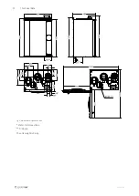
Page 7: ...Technical Data 3 3 1 Dimensions and Weight Fig 2 Dimensions of left hand unit 254496 v01...

Page 8: ...4 Technical Data Fig 3 Dimensions of right hand unit Water coil connections Drainage The unit weight is 56 kg 254496 v01...

Page 9: ...unit is in tended to be stopped by the user manually or due to calendar function we recommend to install air tight dampers at ex tract and supply air ducts The dampers will ensure that no air circulat...

Page 10: ...d be stored and transported in such a way that it is protected against physical damage It should be covered so dust rain and snow cannot enter and damage the unit and its components Important Use the...

Page 11: ...mended installation location for the outdoor air intake is the northern or eastern side of the building and with a distance to openings for discharge of stale ventilation air kitchen ventilator centra...

Page 12: ...8 Installation C concrete bricks W wood block G gypsum M mineral wool X adaptable height according to needs Make sure the mounting bracket is completely level 254496 v01...

Page 13: ...in moisture damage Do not install the ducts directly against structural building elements to avoid sound propagation Use acoustic insulation and sound attenuators Note The type of ventilation ducts a...

Page 14: ...t temperature sensor units with heater 11 Analog input 5 Freely configurable 12 Digital input 1 Rotor guard sensor only for VSR VTR models 13 Digital input 2 Freely configurable Cooker hood VTR 150 K...

Page 15: ...10 V or a digital input 24 V UI1 default configuration Pressure guard UI2 default configuration Cooker hood UI3 default configuration Fire alarm UI4 default configuration Refresh 24V Maximum current...

Page 16: ...ke modifications Choose heating type or none Reset filter changer timer if necessary Finish startup wizard with OK button All additional changes post startup wizard must be recorded in the Commissioni...

Page 17: ...uct is compliant with the European WEEE Directive and related national waste legislation When disposing the unit follow your local rules and regulations This product packing materials are recyclable a...

Page 18: ...l appliances Part 2 40 Particular requirements for electrical heat pumps air conditioners and dehumidifiers EN 50106 Safety of household and similar appliances Particular rules for routine tests refer...

Page 19: ...254496 v01...

Page 20: ...SAVE VTR 250 B Installation instructions 254496 en_GB 2021 03 22 v01 Systemair UAB Lin st 101 LT 20174 Ukmerg LITHUANIA Phone 370 340 60165 Fax 370 340 60166 www systemair com...

Reviews: