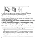
Fig 3-5
1. Connect the male joint of 5-core wires group of the display panel with
the female 5-core terminal of display panel. (See Fig.3-2)
5. Adjust the length of two plastic bolts base on the length of through out from
standard electric cabinet to the wall. Confirm the two bolts fixing in the cabinet
are in the same length and vertical to the wall surface.
6. Fix the bottom cover to the electric cabinet by the accessory slotted head
screws. Confirm the bottom cover is parallel to wall surface. And then reinstall
the bottom cover to centralized controller. (See fig 3-5)
Over tighten the screw would cause rear cover deformed and LCD damage.
When installation, please maintain the screws and wire controller at the same
height level without deformed.
When installation, please reserve a certain length of wire controller connective
cable for future maintenance to take off the wire controller.
2. Please connect the other side of display panel with the wall pre-bedded
5-core cable reliability.
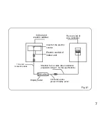
3. Connect the wire control leads from wire controller with the wall pre-bedded
5-core cable reliability. (See Fig.3-3)
4. Take off the screws in the bottom cover of centralized controller by slotted head
screw driver. (See Fig 3-4)
6
NOTE
Summary of Contents for SYSCONTROL WC 90
Page 1: ...SYSCONTROL WC 90 INSTALLATION OWNER S MANUAL GB...
Page 2: ......


