


9
installation manual
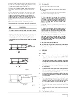
8.2 Drainage Test
Check whether the drainpipe is unhindered
New built house should have this test done before paving
the ceiling.
1 Remove the test cover, and stow water of about 2000ml
to the water receiver through the stow tube.
2 Turn on the power, and operate the air conditioner
under the
"COOLING" mode. Listen to the sound of the
drain pump. Check whether the water is discharged well (a
lag of 1min is allowed before discharging, according to the
length of the drain pipe), and check whether water
leaksfrom the joints.
CAUTIONS: If there is any malfunction, please resolve it
immediately.
3 Stop the air conditioner for there minutes, check if
everything is ok. If the drain hose is located unreasonable,
water overflow will cause the Alarm indicator lamp flashing
(For both cooling and heating type or cooling only type),
even the water leak out from the water receiver.
4 Check the drain pump whether drain water immediately
when alarm sound for the high water lever. If the water
lever can't come down below to the limited water lever, the
air conditioner will stop. Restart it until turn off the power
and drain off all the water.
5 Turn off the power, drain the water away.
The drain plug is used to empty the water-receiver for maintenance
of the air conditioner. Please keep in place at all times during
operation to avoid leakage.
●
●
●
●
●
●
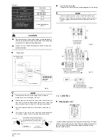
Caution
The air conditioner should use separate power supply with rated
voltage, the voltage of power supply must be within90%~110%
of rated value.
The external power supply to the air conditioner should have
ground wiring, which is linked to the ground wiring of the indoor
and outdoor unit.
The wiring work should be done by qualified persons according
to circuit drawing.
A disconnection device having an air gap contact separation in
all active conductors should be incorporated in the fixed wiring
according to the National wiring regulation.
Be sure to locate the power wiring and the signal wiring well to
avoid cross-disturbance and their contact with connecting pipe
or stop valve body.
The wiring attached to this air conditioner is 6m long. Be sure
to prolong it with wiring of the same type and proper length if
necessary. Generally, do not twist two wiring together unless
the joint is soldered well and covered with insulator tape.
Do not turn on the power until you have checked carefully after
wiring.
The yellow and green wire can only be used to link to the ground
wiring.
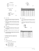
The Specification of Power
●
●
9. WIRING
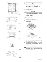
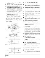
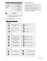
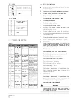
5) When connecting drainpipe, don’t drag the pipe that would pull
the main unit. For this, please arrange bearing points every 0.8 to
1.0 meter to avoid pipe be bended (See
Fig.8-1 b
).
6) When connect a lengthen drainpipe, apply protective tube to
wrap its indoor parts for ensuring the lengthen part connected
tightly.
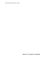
7) In case the drainpipe outlet is higher than pumping connective
pipe of the main body, the drainpipe must be arranged upwards
vertically by using connective assembly of the water outlet for
vertical bending, and the height of the drainpipe shall set to the
defrosting pan surface no more than 600mm, otherwise, too much
backflow while shutdown would leads to overflow (
Refer to
Fig.8-2
).
8) Base on the actual requirement to bend piping, and use
connective assembly of water outlet in terminal box for pipe layout.
CAUTION
The joints in drain system must be sealed to avoid water leakage.
9) The height from floor to the end of drainpipe or the bottom of
drain slot must more than 50 mm. Don’t immerse the end of
drainpipe or the bottom of drain slot into water. When drain
condensate liquid to raceway, please bend the drainpipe to a
U-sharped hydroseal for avoiding stench transmitted by drainpipe
to indoor.
Њ
P
D
!
P
E
Fig.8-1
Gradient:
higher than 1/100
E
<200mm
Lean over 1/100
Pump-pipe clasp
(the fittings)
0.8-1.0m
Fig.8-2
M
ax
. 600m
m


