7
4
Installation
4.1
Unpacking
Verify that all ordered equipment are delivered before starting the installation. Any deviation from the ordered equip-
ment must be reported to the supplier of Systemair products.
4.2
Where/how to install
Danger
• Make sure that the mains to the unit is disconnected before performing any maintenance or electrical
work!
• All electrical connections must be carried out by an authorized installer and in accordance with local rules
and regulations.
Caution
• Take care not to damage the water battery when connecting water pipes to connectors. Use the spanner
to tighten the connection.
Topvex SC03-11 are meant for indoor installation. Topvex SC03-11 can be installed outside if weather protected. Place
the unit on a
horizontal flat surface
. It’s important that the unit is completely levelled before it is put into operation.
Place the unit preferably in a separate room (e.g. storage, laundry room, attic or similar). The electronic components
should not be exposed to lower temperature than 0° C and higher than +50° C.
If the unit is installed in a cold place it is important that the unit is not shut-off by the main switch. As long as the main
voltage is on the electrical cabinet will be kept warm also in cold climates. Although the unit is turned off by the control
system the current is on.
When choosing the location it should be kept in mind that the unit requires maintenance regularly and that the inspec-
tion doors should be easily accessible. Leave free space for opening the doors and for taking out the main components.
Avoid placing the appliance against a wall, as low frequency noise can cause vibrations in the wall even if the fan
noise-level is acceptable. If this is not possible it is recommended to carefully insulate the wall.
The outdoor air intake of the building should if possible be put in the northern or eastern side of the building and away
from other exhaust outlets like kitchen fan outcasts or laundry room outlets.
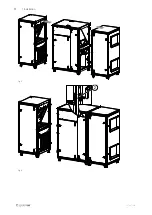
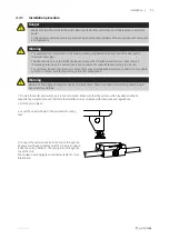
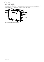
For size SC06-SC11 the units are delivered in parts on the pallet. For mounting procedure, see figure 4 to figure 6. Con-
nect the power supply for the electrical heating battery to the TTC (pos. 1). The cables are marked TTC L1 OUT, TTC L2
OUT and TTC L3 OUT. Attach the fast couplings to the electric wires. Connect the tubes for the pressure guard filter. Push
the units together and fasten the assembly fitting (pos. 2) with a hex key. Make sure that there is enough space behind
the unit to tighten the bolts.
Fig. 4
137667 | A001
Summary of Contents for Topvex SC03-11
Page 4: ......


