2
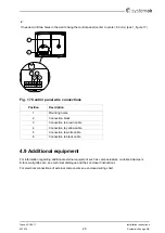
If needed, drill two holes in the wall to hang the control panel (center to center: 60 mm) (pos.1, figure 17).
Fig. 17 Control panel wire connections
Position
Description
1
Mounting holes
2
Connection block
3
Connection to brown cable
4
Connection to yellow cable
5
Connection to white cable
6
Connection to black cable
4.9 Additional equipment
For information regarding additional external equipment such as valve actuators, motorized dampers,
E-tool, wall grilles etc. see technical catalogue and their enclosed instructions
For electrical connections of external components see enclosed wiring chart.
Installation instructions
207575
20
Systemair Sverige AB

