4.3 Condensation drain
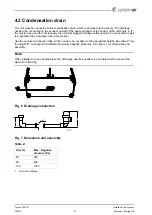
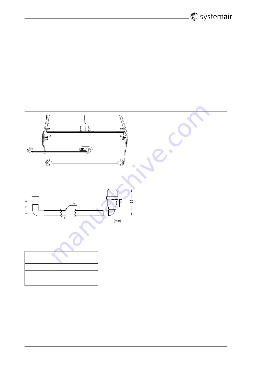
The unit must be connected to the condensation drain, which is enclosed upon delivery. The drainage
needs to be connected on the exhaust air side of the heat exchanger at the bottom of the unit figure 6. If
the unit is to be used for cool recovery the normally plugged drainage outlet needs to be connected as well
to a separate tube and water lock (accessories).
Use the enclosed connection tube, which needs to be cut down to the appropriate height. See table 2 how
the height “H” corresponds to different maximum negative pressures. See figure 7 for dimensions and
assembly.
Note:
When installed in a non heated place the drain pipe and trap needs to be insulated well to prevent the
water from freezing.
Fig. 6 Drainage connection
Fig. 7 Dimension and assembly
Table 2:
H (mm)
Max. Negative
pressure (Pa)
65
300
95
1
600
135
1000
1.
Normal conditions
Installation instructions
207575
9
Systemair Sverige AB


