background image

18

| Installation

4.5.2.3

BMS Connection

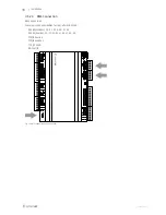
BMS Connection

Communication possibilities for controller E283 WEB.

RS485(Modbus): 50-51-52 or 60-61-62

RS485(Exoline): 50-51-52-53 or 60-61-62-63

• TCP/IP Exoline

• TCP/IP Modbus

TCP/IP WEB

BACnet/IP

Fig. 14 BMS connection on the controller

124454 | A003

Summary of Contents for Topvex SR03

Page 1: ...Document in original language A003 Topvex SR TR03 SR TR04 SR TR06 Compact Air Handling Unit Installation instructions GB ...

Page 2: ... Systemair AB All rights reserved E OE Systemair AB reserves the rights to alter their products without notice This also applies to products already ordered as long as it does not affect the previously agreed specifications ...

Page 3: ...lectrical data Topvex SR TR 03 06 8 3 3 Transport and Storage 9 4 Installation 9 4 1 Unpacking 9 4 2 Where how to install 9 4 3 Installing the Unit 10 4 3 1 Installation procedure 11 4 4 Supply air sensor Topvex SR 03 06 11 4 5 Connections 13 4 5 1 Ducting 13 4 5 2 Electric Connections 15 4 6 Installing the Control Panel 19 4 6 1 Dimensions 19 4 6 2 General information 19 4 6 3 Installation 19 4 7...

Page 4: ......

Page 5: ... ta ag ge e D Diir re ec ct tiiv ve e 2 20 01 14 4 3 35 5 E EU U E EM MC C D Diir re ec ct tiiv ve e 2 20 01 14 4 3 30 0 E EU U T Th he e f fo ollllo ow wiin ng g h ha ar rm mo on niiz ze ed d s st ta an nd da ar rd ds s a ar re e a ap pp plliie ed d iin n a ap pp plliic ca ab blle e p pa ar rt ts s EN ISO 12100 2010 Safety of machinery General principles for design Risk assessment and risk reduct...

Page 6: ...that all joints are covered with insulation and tape well Duct connections duct ends should be covered during storage and installation Do not connect tumble dryers to the ventilation system Take care not to damage the water battery when connecting water pipes to connectors Use a spanner to tighten the connection 3 Product information 3 1 General This installation manual concerns air handling unit ...

Page 7: ...06 Drawn as a right hand unit M Mo od de ell A A B B C C D D c c c c E E c c c c F F SR04 1600 1041 850 1315 565 175 SR06 1600 1128 1000 1468 868 200 M Mo od de ell G G H H II JJ K K SR04 500 171 250 200 355 SR06 600 164 300 200 396 Y 15R 1 2 Inner thread 3 2 1 1 Weights Topvex SR 03 06 M Mo od de ell W We eiig gh ht t k kg g SR03 220 SR04 270 SR06 300 124454 A003 ...

Page 8: ...4 Product information 3 2 1 2 Space required Topvex SR 03 06 Fig 3 Space required M Mo od de ell M M m mm m N N m mm m SR03 650 603 SR04 750 603 SR06 900 603 124454 A003 ...

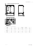
Page 9: ...Dimensions mm TR03 TR04 Drawn as a left hand unit M Mo od de ell A A B B C C D D c c c c E E c c c c F F TR03 1180 1230 750 1048 618 193 TR04 1480 1280 850 1348 718 209 M Mo od de ell G G H H II JJ K K Ø TR03 265 195 260 295 127 250 TR04 354 315 220 315 163 315 124454 A003 ...

Page 10: ...Product information Fig 5 Dimensions mm TR06 Y 15R 1 2 Inner thread 3 2 2 1 Weights Topvex TR 03 06 Drawn as a left hand unit M Mo od de ell W We eiig gh ht t k kg g TR03 230 TR04 290 TR06 360 124454 A003 ...

Page 11: ...Product information 7 3 2 2 2 Space required Topvex TR 03 06 Fig 6 Space required M Mo od de ell M M m mm m N N m mm m TR03 660 570 TR04 760 715 TR06 910 825 124454 A003 ...

Page 12: ...a an nd d 4 40 00 0 V V 3 3N N F Fu us se e m ma aiin ns s A A f fo or r 2 23 30 0V V 1 1 a an nd d 2 23 30 0V V 3 3 SR TR03 EL 1412 3 3x13 3x16 SR TR03 None HWL HWH 1412 10 10 SR TR03 El M0 1014 3 3x13 3x16 SR TR03 None HWH M0 1016 13 13 SR TR04 EL 1460 4 3x16 3x20 SR TR04 None HWL HWH 1460 10 10 SR TR04 El M0 1560 4 3x16 3x20 SR TR04 None HWH M0 1560 10 13 SR TR06 EL 1794 6 3 3x16 3x25 SR TR06 N...

Page 13: ...DS to size 04 and 06 Place the unit on a h ho or riiz zo on nt ta all f flla at t s su ur rf fa ac ce e It s important that the unit is completely levelled before it is put into operation Place the unit preferably in a separate room e g storage laundry room attic or similar The electronic components should not be exposed to lower temperature than 0 C and higher than 50 C If the unit is installed i...

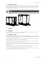
Page 14: ...alled in the following position figure 8 Fig 8 Installation position left hand unit Fig 9 Installation position right hand unit Table 2 Symbol description S Sy ym mb bo oll D De es sc cr riip pt tiio on n Supply air Exhaust air Outdoor air Extract air 124454 A003 ...

Page 15: ...the top of the unit casing Topvex TR 03 06 directly to the electrical connection box See enclosed wiring diagram and below table table 3 for more information Warning The units electrical connection to the mains supply must be preceded by an all pole circuit breaker with a minimum 3 mm gap Danger Make sure that the Mains supply to the unit is disconnected before performing any maintenance or electr...

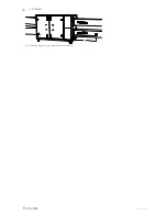
Page 16: ...12 Installation Fig 10 Installed supply air sensor right hand connected unit 124454 A003 ...

Page 17: ...uct and discharge ducts must always be well insulated against condensation Correct insulation installation on ducts connected to the unit is especially important All ducts installed in cold rooms areas must be well insulated Use insulating covering minimum 100 mm mineral wool with plastic diffusion barrier In areas with extremely low out door temperatures during the winter additional insulation mu...

Page 18: ...he duct system silencers should be installed both on supply and extract air To avoid noise being transferred between rooms via the duct system and also to reduce noise from the duct system it self installation of silencers before every inlet diffuser is recommended 124454 A003 ...

Page 19: ...ve been read and understood See the enclosed wiring diagram for internal and external wiring All external connections to possible accessories are made to terminals inside the electrical connection box table 3 Fig 12 Opening the electrical connection box Danger Make sure that the Mains supply to the unit is disconnected before performing any maintenance or electrical work All electrical connections...

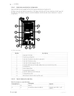
Page 20: ... Regulator E 28 WEB 2 Transformer 230 24V AC 3 Terminals for internal and external components 4 Terminals for internal wiring 5 Terminals for mains supply to the unit 6 Contactor K2 Pump control water HW units only not present in EL units 7 Automatic fuse 8 Electric heater frame 9 Automatic fuse for heater 10 Contactor K3 for control of EL heater 11 Thermostat EL units 12 Manual over heat protecti...

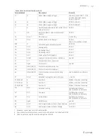
Page 21: ...I 1 Temperature sensor supply air 40 Agnd UI reference neutral 412 UAI 1 UDI 1 Pressure transmitter extract air 422 UAI 2 UDI 2 Pressure transmitter supply air 44 UAI 3 UDI 3 Frost protection sensor water heating battery Use terminal 40 as reference 43 DI ref Extended running Fire alarm reference 24V DC P1 50 P2 60 B Exo line B Modbus Exo line connection P 151 P2 61 A Exo line A Modbus Exo line co...

Page 22: ...MS Connection Communication possibilities for controller E283 WEB RS485 Modbus 50 51 52 or 60 61 62 RS485 Exoline 50 51 52 53 or 60 61 62 63 TCP IP Exoline TCP IP Modbus TCP IP WEB BACnet IP Fig 14 BMS connection on the controller 124454 A003 ...

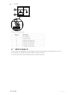
Page 23: ...x Cable length is 10 m In case the control panel needs to be detached from the signal cable it is possible to loosen the wires on the back of the control panel figure 16 A set of self adhesive magnet strips are included in the package to facilitate installation on a metal surface 4 6 3 Installation 1 1 Find an appropriate place to install the control panel Max imum length between control panel and...

Page 24: ...ection to yellow cable 5 Connection to white cable 6 Connection to black cable 4 7 Additional Equipment For information concerning additional external equipment such as valve actuators motorized dampers E tool roof units wall grilles etc see technical catalogue and their enclosed instructions For electrical connections of external components see enclosed wiring chart 124454 A003 ...

Page 25: ...124454 A003 ...

Page 26: ......

Page 27: ......

Page 28: ... Installation instructions 124454 en_GB 15 03 2016 A003 Systemair Sverige AB Industrivägen 3 SE 739 30 Skinnskatteberg Sweden Phone 46 222 440 00 Fax 46 222 440 99 www systemair com ...

Reviews: