background image


    ____________________________________________________________________________________________________ 
    Topvex SR07, SR09, SR11

 E


Installation instruction 


    205870


Systemair AB


13

Ducting 

 
Air to and from the unit is led through a duct system. To ensure long life and satisfactory cleaning 
possibilities, ducts made of galvanized steel are highly recommended. 
To obtain high efficiency, low energy consumption and the required airflow, the duct system should be 
commissioned for low air speeds and low pressure drops. 


NOTE! 


Do not connect tumble dryers to the ventilation system 


Duct connections/duct ends should be covered during storage and installation 


Grilles for discharge/roof units must be installed according to building regulations in force.


Duct connections 

To ensure air tightness the connections needs sealing strips or sealing compound between the ducts and 
the unit. 


Attention 

To avoid fan noise being transferred via the ducting system, silencers should be installed both on supply 
and extract air. 


Condensation/heat insulation. 

All the air ducts must be well insulated against condensation. To obtain the heat recovery efficiency it is 
especially important to insulate the Supply and Extract air ducts against heat losses. Use insulating 
covering (minimum 100 mm mineral wool) with plastic diffusion barrier. 
In areas with extremely low outdoor temperatures during the winter, additional insulation must be installed. 

Total insulation thickness must be at least 150 mm.


NOTE! If the unit is installed in a cold place make sure that all joints are well taped and covered 
with insulation. 
 

Electrical connection 

The unit must not be put into operation before all the electrical safety precautions have been read and 
understood. 


Electrical connections must be made by authorized installer and in accordance with current  
wiring regulations. 

 
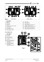
See 

fig. 2 

where to find the electrical connection box. 

 
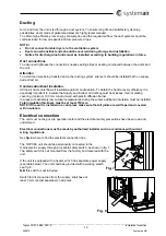
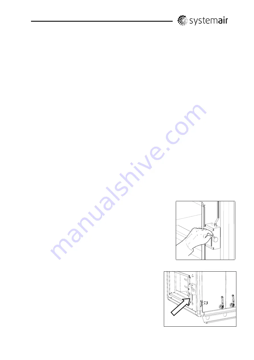
The TOPVEX unit should be permanently connected to the  
mains electric supply through a lockable safety switch, as shown in fig. 7. 
The safety switch is not mounted from the factory but delivered with the 
unit. 
 
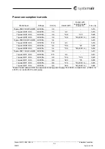
If the unit is equipped with a heater, which has separate power supply   
(see table below). The unit shall bee provided with a working switch,  
see fig. 8.  

N.B

 this switch is not included. 

 
Switch for disconnection from the supply, shall have at  
least 3 mm contact separation in all poles. 


Fig. 7 

Fig. 8 

Summary of Contents for Topvex SR07 E

Page 1: ...Corrigo ver no 3 0 1 03 Topvex SR07 SR09 SR11 E Compact Air Handling Unit Installation instruction GB GB...

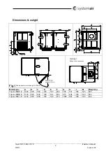
Page 2: ...struction 205870 Systemair AB 2 Dimensions weight Fig 1 Optional Exhaust top connection Model spec A B C D E F G K L M Weight kg Topvex SR07 E 1000 600 300 125 150 200 795 337 195 145 320 Topvex SR09...

Page 3: ...sor supply air filter 14 Electrical Heater Water coil 6 Fan extract air 15 Electrical Connection box see fig 3 7 Fan supply air 16 Pressure sensor extract air filter 8 Control Heat exchanger 17 Pressu...

Page 4: ...r extract air accessories 2 Extract air 7 Damper and motor exhaust air accessories 3 Exhaust air 8 Damper and motor outside air accessories 4 Outside air 9 Sensor supply air 5 VAV pressure transmitter...

Page 5: ...5 Table of contents 5 Declaration of Conformity 6 Electrical connection 7 Description of functions Topvex SR E EL 8 Description of functions Topvex SR E HW 9 Dimension and Weight 10 Transport and sto...

Page 6: ...00 1 Safety of machinery Basic concepts general principles for design Part 1 Basic terminology methodology EN ISO 12100 2 Safety of machinery Basic concepts general principles for design Part 2 Techni...

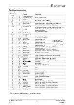
Page 7: ...r 37 G0 Neutral Damper outdoor air Water valve actuator cooling EL units only 38 G 24V AC Damper outdoor air Water valve actuator cooling EL units only 39 DO 24V AC 0 5A Water pump control voltage con...

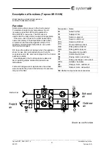
Page 8: ...amper when the appliance is stopped In case of an unintended stop on the rotor a signal is sent to RC which is displayed on the Control panel as an alarm Also displayed in the Control panel are date a...

Page 9: ...ans have stopped DO closes the outdoor air damper when the appliance stops In case of an unintended stop on the rotor a signal is sent to RC which is displayed on the Control panel as an alarm Also di...

Page 10: ...t do not try to slide the unit into place after it has been put down on the ground Where how to Install The unit is meant for horizontal installation The electronic components should not be exposed to...

Page 11: ...port to the site of installation How to split the unit A Loosen the cable connectors in the wall B The two halves of the appliance are joined using 4 M10 screws one in each corner C Control section D...

Page 12: ...se have hexagonal connectors internal threaded tube Cover plates around the pipes are fixed to the unit reinforcement Note Take care not to damage the water battery when connecting water pipes to conn...

Page 13: ...n To obtain the heat recovery efficiency it is especially important to insulate the Supply and Extract air ducts against heat losses Use insulating covering minimum 100 mm mineral wool with plastic di...

Page 14: ...opvex SR07 E EL 400V3N 3 0 12 0 30 230V 3 3x40 Topvex SR09 E HWL HWH 400V3N 5 4 3x10 Topvex SR09 E EL 400V3N 11 9 4 5 3x16 Topvex SR09 E EL 400V3N 5 4 15 0 22 3x32 Topvex SR09 E EL 400V3N 5 4 15 0 38...

Page 15: ...ly voltage 24V AC Control signal 0 10 V can be connected to the unit and be operated in sequence to the heater battery A DX cooler can be connected to the unit See page 6 to see which terminal blocks...

Page 16: ...If there is still a risk of freezing the unit is stopped and the outdoor sir dampers accessory are closed Control panel The SCP control panel is delivered with a 10m cable that is pre connected to the...

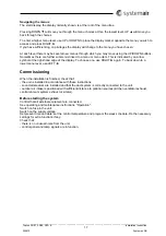
Page 17: ...to a menu or menu item This is indicated by an arrow symbol at the right hand edge of the display To choose one use RIGHT again To back down to a lower menu level use LEFT Commissioning When the insta...

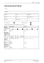
Page 18: ...UIRUPHG XQFWLRQ HIDXOW VHWWLQJ 6HW YDOXH 7HPS RQWURO IXQFWLRQ WHPS 6XSSO WUDFW 5RRP 6XSSO WUDFW 5RRP 6HW SRLQW 2XWGRRU WHPS FRPSHQVDWHG VXSSO DLU FRQWURO 2XWGRRU VXSSO DLU WHPS 3RLQW DQG 3RLQW DQG 3RL...

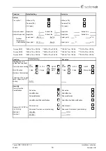
Page 19: ...RU 3D P K RU 3D XQFWLRQ HIDXOW VHWWLQJ 6HW YDOXH RROLQJ ORJRQ WR V VWHP OHYHO UHTXLUHG RQWURO IXQFWLRQ FRROLQJ 1RW DFWLYH 9 2Q 2II 1RW DFWLYH 9 2Q 2II 2Q RII IXQFWLRQ VWHS VWHS LQDU VWHS VWHS VWHS LQ...

Page 20: ...DQG KROLGD V 3HULRG WR 0RQGD WR 6XQGD DQG SXEOLF KROLGD V WR RII SHULRG 2 6 1RUPDO IDQ VSHHG KDV SULRULW RYHU D UHGXFHG IDQ VSHHG HHNGD 3HULRG 1RUPDO IDQ VSHHG 5HGXFHG IDQ VSHHG 0RQGD 7XHVGD HGQHVGD 7...

Page 21: ...WHPSHUDWXUHV KLJKHU WKDQ 6WRSSHG DW RXWGRRU QLJKW WHPSHUDWXUHV KLJKHU WKDQ 6WRSSHG DW RXWGRRU QLJKW WHPSHUDWXUHV ORZHU WKDQ 6WRSSHG DW URRP WHPSHUDWXUHV ORZHU WKDQ RXU IRU VWDUW VWRS 6WDUW 6WRS 6WDUW...

Page 22: ...QWLQXRXV UXQ LUH QSXW 1RUPDOO RSHQHG 1RUPDOO RSHQHG 1RUPDOO FORVHG 1RUPDOO FORVHG WHUQDO 6HW SRLQW QRE WHUQDO VHW SRLQW NQRE 2II 2Q 2II 0LQ VHW SRLQW RI NQRE 0D VHW SRLQW RI NQRE HDW 3XPS 3XPS VWRS PR...

Page 23: ...DUP ODVV 1RW DFWLYH ODVV HOD V HOD V 7KH XQLW VWRSSHG DW DODUP 1R 7KH XQLW VWRSSHG DW DODUP 1R 0DOIXQFWLRQ 3 FRROLQJ ROG ZDWHU SXPS DLOXUH RI DLU VXSSO ODVV 1RW DFWLYH ODVV HOD V HOD PLQ 7KH XQLW VWRS...

Page 24: ...VV 1RW DFWLYH ODVV 1RW DFWLYH HOD V HOD V 7KH XQLW VWRSSHG DW DODUP 1R 7KH XQLW VWRSSHG DW DODUP 1R RZ URRP WHPSHUDWXUH RZ H KDXVW WHPSHUDWXUH ODUP VHWWLQJV HI VHWWLQJ 6HW YDOXH ODUP VHWWLQJV HI VHWWL...

Page 25: ...RW DFWLYH HOD PLQ HOD V 7KH XQLW VWRSSHG DW DODUP HV 7KH XQLW VWRSSHG DW DODUP 1R DUJHVW GLII EHWZHHQ PXVW LV YDOXH 3D ODUP VHWWLQJV HI VHWWLQJ 6HW YDOXH ODUP VHWWLQJV HI VHWWLQJ 6HW YDOXH 0DQXDO KHDW...

Page 26: ..._____________________________________________________________________________________________________ Topvex SR07 SR09 SR11 E Installation instruction 205870 Systemair AB 26 Notes...

Page 27: ......
Page 28: ...ves the right to make changes and improvements to the contents of this manual without prior notice Systemair AB Industriv gen 3 739 30 Skinnskatteberg Phone 46 222 440 00 Fax 46 222 440 99 www systema...

Reviews: