____________________________________________________________________________________________________
Topvex SR07, SR09, SR11
E
Installation instruction
205870
Systemair AB
15
External connections
See
page 6
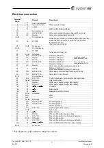
and the attached wiring diagram, how to connect the electrical cables.
Timer (
Extended operation)
When the unit is running on reduced speed or is in shutdown mode it can be forced up one step as long as
the timer switch is closed. Set the
Extended operating
in the control panel to 0 minutes.
Push button (
Extended operation)
When the unit is running on reduced speed or is in shutdown mode it can be forced up one step by using a
Push button (impulse). Set the
Extended operating
in the control panel to the required time, in minutes.
Damper, outdoor/exhaust air
The outdoor / exhaust air damper (Supply voltage 24V AC, Spring return) is used to avoid cold air to enter
the building when the unit is stopped e.g. during the night.
See
fig. 4
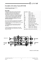
where to assemble the dampers and page 6 how to connect the electrical wiring.
The damper is also preventing the hot water battery (HW models) from freezing by closing when the
returning water in the battery is below a set temperature, +7
C.
Cooling battery
A water valve actuator (Supply voltage 24V AC, Control signal 0-10 V) can be connected to the unit and be
operated in sequence to the heater battery.
A DX-cooler can be connected to the unit.
See page 6 to see which terminal blocks to use.
HW valve/actuator
A water valve actuator (Supply voltage 24V AC, Control signal 0-10 V) can be connected to the unit to
control a 2 or 3-way water valve.
See page 6 to see which terminal blocks to use.
Fire alarm
Connects to an external fire central. Choose if the unit should stop or run on normal fan speed when the
alarm is activated. The Alarm activates thru a digital input DI that can be set to normal open or normal
closed.
Room sensor
A room sensor can be connected to the unit. UAI3 on terminal block 58 (see page 6) can be configured for
this purpose.
E-Tool (commissioning software)
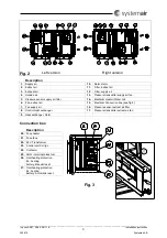
Wirings are to be connected directly to the Corrigo E28 controller (see fig.3 pos.23) on terminal 50-52 (B,
A, N).
N.B.
For more detailed information see the instruction attached to the E-Tool software program.
Communication to BMS (Building Management System)
Exoline and Modbus via a built in RS-485 contact is included as standard.
LON and Exoline via TCP/IP are available as accessories.
Communication wirings are to be connected directly to the Corrigo E28 controller (see fig.3 pos.23) on
terminal 50-53 (B, A, N, E), 57-59 (Net+, Net-, Egnd) or the TCP/IP terminal.
N.B.
For more detailed information see the attached
Corrigo E – User Manual.
Summary of Contents for Topvex SR07 E
Page 27: ......


