background image

Installation |

13

4.6.2

Condensation and Heat Insulation

Outdoor air duct and exhaust ducts must always be well insulated against condensation. Correct insulation installation
on ducts connected to the unit is especially important. All ducts installed in cold rooms/areas must be well insulated.
Use insulating covering (minimum 100 mm mineral wool) with plastic diffusion barrier. In areas with extremely low out-
door temperatures during the winter, additional insulation must be installed. Total insulation thickness must be at least
150 mm.

Caution

• If the unit is installed in a cold place make sure that all joints are covered with insulation, and tape well

• Duct connections/duct ends should be covered during storage and installation

• Do not connect tumble dryers to the ventilation system

4.6.3

Silencers

To avoid fan noise being transferred via the duct system, silencers should be installed both on supply and extract air.

To avoid noise being transferred between rooms via the duct system and also to reduce noise from the duct system it-
self, installation of silencers before every inlet diffuser is recommended.

131677 | A004

Summary of Contents for Topvex SX/C Series

Page 1: ...Document in original language 131677 A004 Topvex SX C Topvex TX C Air Handling Unit Installation instructions GB...

Page 2: ...131677 A004...

Page 3: ...ing 8 4 2 Where how to install 8 4 3 Condensation drain 9 4 4 Installing the unit 10 4 4 1 Installation procedure 10 4 5 Supply air sensor Topvex SX C 11 4 6 Connections 12 4 6 1 Ducting 12 4 6 2 Cond...

Page 4: ......

Page 5: ...ed standards are applied in applicable parts EN ISO 12100 2010 Safety of machinery General principles for design Risk assessment and risk reduction EN 13857 Safety of machinery Safety distances to pre...

Page 6: ...d place make sure that all joints are covered with insulation and tape well Duct connections should be covered during storage and installation Do not connect tumble dryers to the ventilation system Ta...

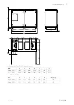
Page 7: ...G H K Topvex SX C03 877 500 250 170 200 188 1041 1772 1926 Topvex SX C04 877 600 300 163 200 138 1127 1905 2060 Topvex SX C06 877 600 300 235 342 138 1412 21871 2344 1 SX C06 has 4 extra feet Model L...

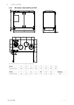
Page 8: ...02 B 58 45 E C F G H I J K K L K O 120 N K L M 87 Fig 1 Dimensions mm Topvex SX C03 drawn as left hand unit Model A B C D E F G H Topvex TX C03 1587 1210 880 1435 725 240 348 410 Model I J K L M N O W...

Page 9: ...s mm Topvex TX C04 06 drawn as left hand unit Model A B C D E F G Topvex TX C04 1860 1279 880 1708 725 104 136 Topvex TX C06 2150 1630 880 19981 725 116 196 1 TX C has 4 extra feet Model H I J K L M W...

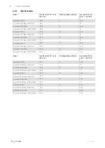
Page 10: ...3x32 Topvex SX C06 None HWL HWH 1780 3x10 Topvex SX C06 EL M0 2124 16 3x32 Topvex SX C06 None HWL HWH M0 2124 3x10 Model Fans W tot 230V 1 and 400 V 3N El Heating battery kW tot Fuse mains A for 230...

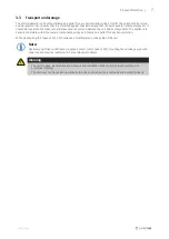
Page 11: ...livered complete with all necessary components wrapped in plastic on a pallet for easy transportation When transporting the Topvex SX C TX C units use a forklift placed on the gable of the unit Note N...

Page 12: ...binet will be kept warm also in cold climates When choosing the location it should be kept in mind that the unit requires maintenance regularly and that the inspec tion doors should be easily accessib...

Page 13: ...d as well to a separate tube and water lock accessories Use the enclosed connection tube which needs to be cut down to the appropriate height See table 1 how the height H corresponds to different maxi...

Page 14: ...ption Symbol Description Supply air Exhaust air Outdoor air Extract air 4 4 1 Installation procedure 1 Prepare the surface where the unit is to be mounted Make sure that the surface is flat levelled a...

Page 15: ...ly to the unit is disconnected before performing any maintenance or electrical work All electrical connections must be carried out by an authorized installer and in accordance with local rules and reg...

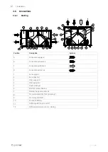
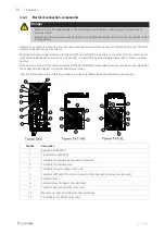
Page 16: ...air D Connection extract air 1 Fan supply air 2 Fan extract air 3 Filter supply air 4 Filter extract air 5 Heat exchanger 6 Electrical connection box 7 Damper by pass outdoor air 8 Pressure transmitte...

Page 17: ...tion must be installed Total insulation thickness must be at least 150 mm Caution If the unit is installed in a cold place make sure that all joints are covered with insulation and tape well Duct conn...

Page 18: ...it is reachable by unscrewing the lower hatch to the re heater battery The unit must not be put into operation before all the electrical safety precautions have been read and understood See the enclos...

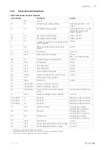
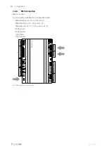
Page 19: ...ensor reference neutral 31 AI 1 Temperature sensor supply air 40 Agnd UI reference neutral 412 UAI 1 UDI 1 Pressure transmitter extract air 422 UAI 2 UDI 2 Pressure transmitter supply air 44 UAI 3 UDI...

Page 20: ...cation possibilities for controller E283 WEB RS485 Modbus 50 51 52 or 60 61 62 RS485 BACnet 50 51 52 or 60 61 62 RS485 Exoline 50 51 52 53 or 60 61 62 63 TCP IP Exoline TCP IP Modbus TCP IP WEB TCP IP...

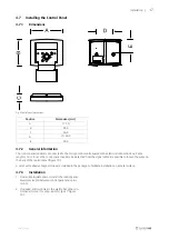
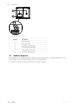
Page 21: ...10 m In case the control panel needs to be detached from the signal cable it is possible to loosen the wires on the back of the control panel figure 10 A set of self adhesive magnet strips are includ...

Page 22: ...able 5 Connection to white cable 6 Connection to black cable 4 8 Additional Equipment For information concerning additional external equipment such as valve actuators motorized dampers E tool roof uni...

Page 23: ...131677 A004...

Page 24: ...pvex SX C Topvex TX C Installation instructions 131677 en_GB 2017 04 28 A004 Systemair Sverige AB Industriv gen 3 SE 739 30 Skinnskatteberg Sweden Phone 46 222 440 00 Fax 46 222 440 99 www systemair c...

Reviews: