Page 14
4.3 External hydraulic circuit
The flow switch and the filter water, although not in-
cluded in the supply, must always be fitted such as
plant components.
Their installation is mandatory for warranty.
The external hydraulic circuit must ensure
the water flow to the evaporator under any
working or adjustment conditions.
The external hydraulic circuit should consist of the fol-
lowing elements:
n
A circulation pump that can ensure the necessary
capacity and discharge head.
n
The capacity of the primary hydraulic circuit should
not be less than 7.5 litres/KW of cooling capacity,
in order to prevent the repeated startup of the com-
pressor and any damage to it. If the water capacity
in the primary piping of the circuit and in the evapo-
rator is lower than this value, an insulated storage
tank shall be installed.
n
A membrane expansion vessel provided with safety
valve with vent, that must be visible.
The capacity of the expansion vessel must
allow for an expansion of at least 2% of the
volume of the fluid in the circuit (evaporator,
piping, user circuit and standby tank, if any).
The expansion vessel needs not be isolated,
because no water can circulate inside it.
n
A flow switch, to disable the appliance when the
water is not circulating.
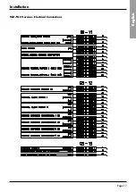
The flow switch must be connected (terminals
1-2) as shown in the wiring diagram of the
“User’s Terminal Box” (Paragraph 4.7).
To install the flow switch, follow the man-
ufacturer’s instructions.
As a general rule, the flow switch shall be mounted on
a horizontal pipe, at a distance from the curves equal
to 10 times the diameter of the pipe and far from
valves or other components that are likely to hinder the
water flow upstream of or downstream from the flow
switch.
n
The bleed valves must be mounted on the highest
point of the piping.
n
The stop valves must be mounted on the piping of
the water entering/leaving the condenser.
n
The discharge points (provided with plugs, cocks
etc.) must be arranged in the lowest point of the pip-
ing.
WARNING
NOTE
RECOMMENDED WATER COMPOSITION
PH
7,5 - 9
Electrical conductivity
10 - 500
μS/cm
Total hardness
4,5 - 8,5
dH
Temperature
< 60
[°C]
Alkalinity (HCO
3
-
)
70-300
ppm
Alkalinity / Sulphates (HCO
3
-
/ SO
4
2-
)
> 1
ppm
Sulphates (SO
4
2-
)
< 70
ppm
Chlorides (Cl
-
)
< 50
ppm
Free Chlorine
< 0,5
ppm
Phosphates (PO
4
3-
)
< 2
ppm
Ammonia (NH
3
)
< 0,5
ppm
Ammonium Ion (NH
4
+
)
< 2
ppm
Manganese Ion (Mn
2+
)
< 0,05
ppm
Free Carbon Dioxide (CO
2
)
< 5
ppm
Hydrogen Sufide (H
2
S)
< 0,05
ppm
Oxygen Content
< 0,1
ppm
Nitrates (NO
3
-
)
< 100
ppm
Manganese (Mn)
< 0,1
ppm
Iron (Fe)
< 0,2
ppm
Aluminium (Al)
< 0,2
ppm
Caution
If the water circuit is to be drained for a time exceeding one month, the circuit must
be fully charged with nitrogen to prevent any risk of corrosion by differential venting
Installation
3)Check AVM’s heights refers to assembly’s instruc-
tions enclosed to the accesory and regulate it using
an adeguate spanner.
4)Lock in position with washer and low nut.
At the end of this operation, make sure the machine
is elastic on the axes and compensating antivibration
joints can be fitted in the water connections.
WARNING


