Page 50
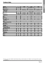
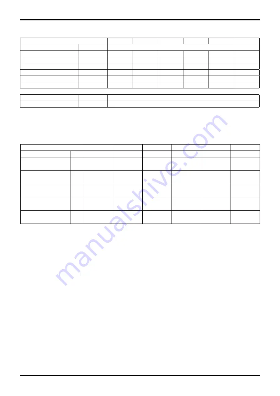
Technical data
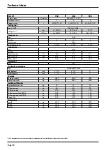
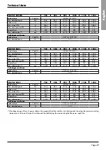
Compressor electrical data
VLH/VLC
704
804
904
1004
1104
1204
Number
4
4
4
4
4
4
Nominal power input
kW
(12,5+17,2)
x2
(15,9+15,9)
x2
(15,9+22,3)
x2
(22,3+22,3)
x2
(22,3+25,5)
x2
(25,5+25,5)
x2
Max. absorbed power
kW
(15,9+21,5)
x2
(22,6+22,6)
x2
(22,6+26,0)
x2
(26,0+26,0)
x2
(26,0+35,0)
x2
(35,0+35,0)
x2
Rated current
A
(36,0+51,0)
x2
(40,0+40,0)
x2
(40,0+48,5)
x2
(48,5+48,5)
x2
(48,5+63,0)
x2
(63,0+63,0)
x2
Max current
A
(160+215)
x2
(225+225)
x2
(225+272)
x2
(275+272)
x2
(272+310)
x2
(310+310)
x2
Oil pan resistor
W
(75+75)
x2
(120+120)
x2
(120+150)
x2
(150+150)
x2
(150+150)
x2
(150+150)
x2
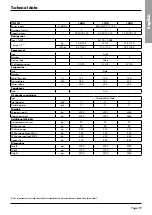
VLH/VLC HPF
704
804
904
1004
1104
1204
Rated voltage
V/ph/Hz
400 (±10%) /3/50
Max. absorbed power
kW
81,4
97
106
112,8
130,8
148,8
Rated current
A
111,1
119,1
140,8
158,8
170,8
182,8
Max. current FLA
A
185,1
171,1
191,8
208,8
237,8
266,8
Max. start-up current LRA
A
349,1
356,1
376,8
432,3
484,8
513,8
External fuses
A
250
250
250
250
315
315
Max. cable section (*)
mm
2
3x120
3x120
3x120
3x120
3x185
3x185
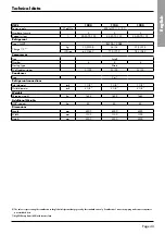
Exchanger resistance
Rated voltage
V/ph/Hz
230/ (± 10%)/1/50
Max. absorbed power
W
130
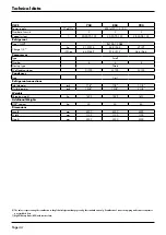
(*) The dimensioning of the unit’s power cables is the responsibility of the installer, who shall consider: the rating, the maximum working
temperature in the room, the type of insulation and the cable laying, the maximum length of the power supply line.


