Page 52
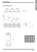
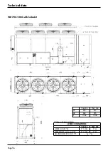
* Dimensions are referred to unit with antivibration mounted isolators.
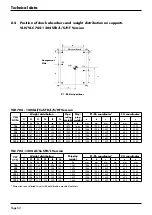
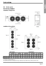
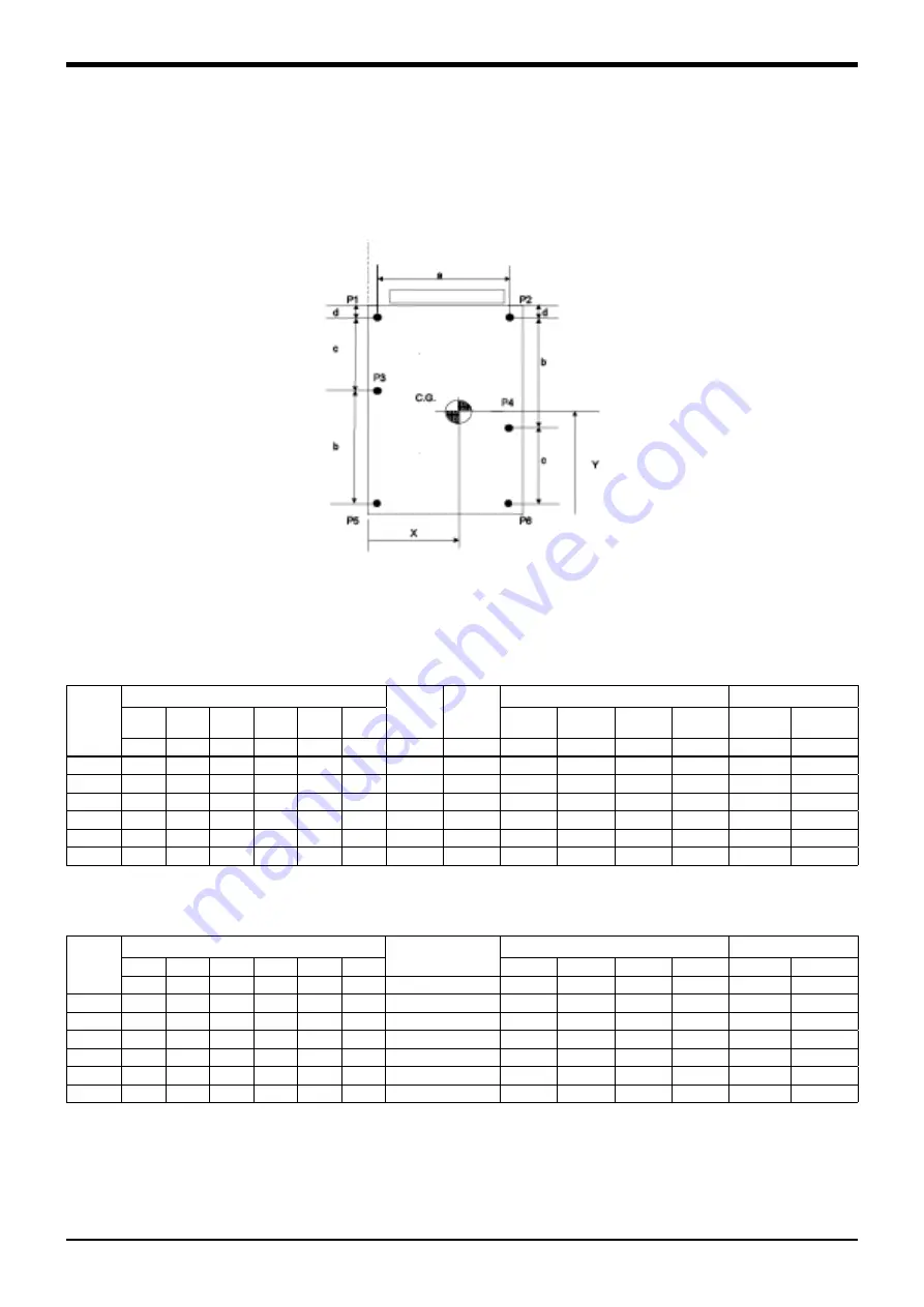
8.4 Position of shock absorbers and weight distribution on supports
VLH/VLC 704-1204 STD/L/S/HT Version
P1 - P6 Unit positions
Compressor
Side
Electrical board
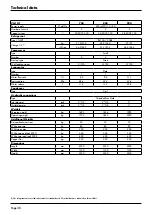
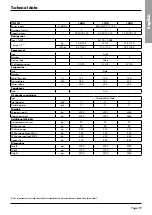
Technical data
VLH
Al/Cu
Weight distribution
Ope-
rating
weight
Ship-
ping
weight
P1-P6 coordinates*
CG coordinates
F1
F2
F3
F4
F5
F6
a
b
c
d
x
y
kg
kg
kg
kg
kg
kg
kg
kg
mm
mm
mm
mm
mm
mm
704
347
293
310
248
265
211
1675
1663
1044
1985
1629
190
480
2200
804
393
316
347
260
291
214
1820
1806
1044
1985
1629
190
480
2200
904
431
337
383
278
324
230
1980
1955
1044
1985
1629
190
480
2200
1004
458
367
405
303
341
250
2125
2100
1044
1985
1629
190
480
2200
1104
468
387
416
322
351
270
2215
2190
1044
1985
1629
190
480
2200
1204
471
388
418
324
354
271
2225
2200
1044
1985
1629
190
480
2200
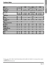
VLH 704 - 1204 Al/Cu STD/L/S/HT Version
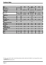
VLC
Al/Cu
Weight distribution
Shipping
weight
P1-P6 coordinates*
CG coordinates
F1
F2
F3
F4
F5
F6
a
b
c
d
x
y
kg
kg
kg
kg
kg
kg
kg
mm
mm
mm
mm
mm
mm
704
311
250
264
192
206
144
1367
1044
1985
1629
190
475
2286
804
355
272
296
202
226
143
1494
1044
1985
1629
190
459
2321
904
383
293
315
211
233
143
1578
1044
1985
1629
190
456
2353
1004
399
303
327
214
238
141
1622
1044
1985
1629
190
452
2369
1104
402
306
329
217
240
145
1639
1044
1985
1629
190
454
2366
1204
403
307
330
218
240
144
1642
1044
1985
1629
190
453
2368
VLC 704 - 1204 Al/Cu STD/L Version

