background image

32

33

tube·amp·company

tube·amp·company

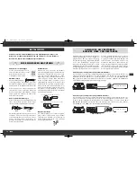
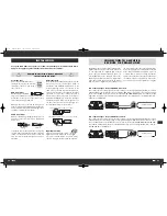
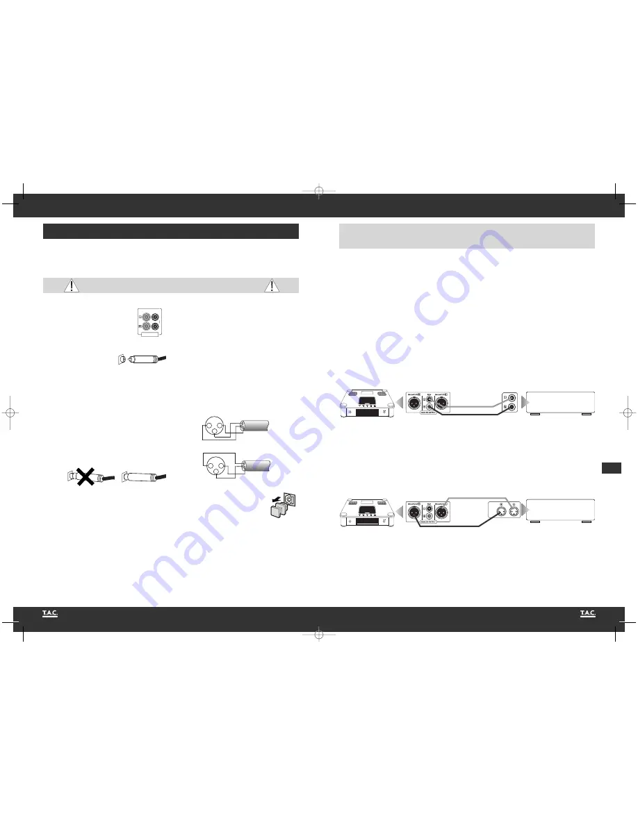
INSTALLATION

Set up the cable links in a sequence as follows. Connect the power cable between device
and power supply only after all other connections have been made.

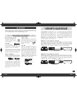
Protective caps 

Prior to the first installation the pro-
tective plastic caps must be removed 
from all the connections used at the 
rear of the unit.

RCA connections

Mechanically identical RCA 
plugs are available for analogue and digital out-
puts. Make sure that you do not get these connec-
tions confused during installation! 

Make sure that you do not mix up the analogue con-
nectors for right and left. The RCA plugs for these are
mostly colour coded as follows: red for the right chan-
nel, black or white for the left channel.

Cable connections

Make sure that all plugs fit tightly. Inadequate con-
nections can cause noise interference, failures and
malfunctions. 

To make the most of the components’ sound poten-
tial, only high quality loudspeakers and connecting
cables, for example Vincent cables, should be
used. Your local stockist will be glad to advise you
about this.

    1

    2

O U

O U T P U T

- wrong -

- correct -

DURING INSTALLATION PLEASE OBSERVE 

THE FOLLOWING ADVICE:

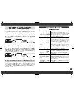
1. USA System (Pin 2 = COLD,  Pin 3 = HOT)

2

1

3

HOT

GND

COLD

2. Europäisches System (Pin 2 = HOT,  Pin 3 = COLD)

2

1

3

HOT

GND

COLD

US System

European System

XLR connections

Note that European and US XLR signal use is diffe-
rent. This device uses the European system in
accordance with Standard AES14-1992 of the
Audio Engineering Society. The structure of the
cable is in any event the same. Provided both con-
nected devices meet the same standard, the signal
connection is correct. This is always the case if
both were manufactured by T.A.C. If two devices
with different standards are connected, the signal
will then be inverted. In this case the signal use on
one side of the connection must be changed. Your
specialist dealer will assist you with this.

Optical Connection

The dust cap protecting the optical 
digital input should only be removed 
if a cable is inserted. After a connection is remo-
ved from this input, the cap should be replaced.

C-60

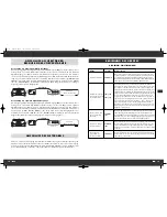
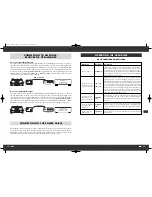
CONNECTION TO AMPLIFIER, 

RECEIVER OR PREAMPLIFIER

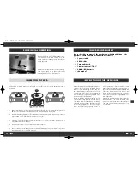
The C-60 has two analogue signal outputs and two
digital output connections on the back of the devi-
ce. The signal from the integrated D/A converter
can be input to a traditional analogue audio com-
ponent (amplifier) via the analogue outputs (13).
On the digital outputs (14) there is a digital output
audio signal which can be processed by external
D/A converters or digital processors. Only one of

Amplifier, Receiver

LINE IN

CD

Use of the analogue output with XLR connector

This is where the stereo audio signal converted to analogue by the high quality integrated D/A converter
and amplified by the internal tube stage is output symmetrically. Two XLR cables are required for connec-
tion to an amplifier. Connect the XLR connectors “L” and “R” in the field “ANALOG OUTPUT BALANCED”
(13) with the left and right connectors of the XLR amplifier input which is usually labelled “CD,” “XLR IN,”
“BALANCED IN” or “FRONT R/L”.

Amplifier, Receiver

CD

Use of the analogue output with RCA connectors

This is where the stereo audio signal converted to analogue by the high quality integrated D/A converter
and amplified by the internal tube stage is output. An RCA cable is required for connection to an ampli-
fier. Connect the RCA connectors “L” and “R” in the field “ANALOG OUTPUT RCA” (13) with the left and
right audio connectors of the amplifier input (standard high level input) which is usually labelled “CD,”
“LINE IN” or “FRONT R/L”.

the four outputs needs to be connected to play CDs.
Select the appropriate connection between the CD
player and your amplifier, preamplifier, receiver or
converter. Bear in mind when doing this that the
special sound qualities of the player's tube ampli-
fier stage will only be exploited if one of the analo-
gue outputs (13) is used to output the music signal.

RCA connection 

XLR connection 

C-60

BALANCED IN

C-60  24.04.2009  16:53 Uhr  Seite 32

Summary of Contents for C-60

Page 1: ...nd FET Verst rkung CD player with Tube FET amplification Lecteur de CD Tube FET t u b e a m p c o m p a n y Bedienungsanleitung deutsch Instructions for use english Manuel d utilisation fran ais C 60...

Page 2: ...w nscht Ihnen Ihr T A C Team Dear Customer we thank you for the confidence you prove in purchasing our product It will match your high demands towards sound and manufacturing quality Though it is unde...

Page 3: ...etriebener Ger te mit Fl ssigkeiten Feuchtigkeit Regen oder Wasserdampf ist f r diese Ger te und deren Benut zer gef hrlich und unbedingt zu vermeiden Achten Sie darauf dass weder Fl ssigkeiten noch O...

Page 4: ...r Hinsicht au ergew hnliches und exklusi ves System dessen Klang Verarbeitungsqualit t und Eleganz heutzutage nicht allt glich sind INBETRIEBNAHME Nach dem Auspacken entfernen Sie bitte die Schaumstof...

Page 5: ...lsprung vorw rts 12 TUBE FET Betriebsart Umschalter Betriebsart zwischen R hrenverst rkung und Transistorverst rkung umschalten VORDERANSICHT 1 12 2 3 4 13 ANALOG OUTPUT analoge Tonsignalausg nge Entw...

Page 6: ...ge n dert werden Wechsel Einlegen der Batterien a ffnen und entfernen Sie den Batteriefach deckel der Fernbedienung indem Sie ihn mit kr ftigem Zug an der Lasche am Rand der Fernbedienung anheben Der...

Page 7: ...erden Bevorzugen Sie geschirmte Audio Kabel Ihr Fachh ndler wird Sie gern diesbez glich beraten 1 2 OU OUTPUT Falsch Richtig ZUR BESONDEREN BEACHTUNG 1 USA System Pin 2 COLD Pin 3 HOT 2 1 3 HOT GND CO...

Page 8: ...d an der Ger tevorderseite ein und ausgeschaltet Im ausge schalteten Zustand ist es vom Stromnetz getrennt Vor dem Einschalten sollte vorsichtshalber die Lautst rkeeinstellung des Verst rkers reduzier...

Page 9: ...nden Titels wechseln NEXT 11 23 W hrend der CD Wiedergabe wird nach Bet tigung dieser Taste das Abspielen des aktuellen Titels angehalten und die Wiedergabe des in der Reihenfolge n chsten Titels bego...

Page 10: ...aktuelle Titel fortw hrend wie derholt nachdem seine Spielzeit abgelaufen ist In der Anzeige 4 ist die ser Betriebszustand durch den Schriftzug REPEAT 1 gekennzeichnet Wurde die Taste zweimal bet tigt...

Page 11: ...en FEHLERSUCHE Symptom M gliche Fehlerursache Abhilfe Keine Funktion nach Bet tigung des Netzschalters Netzkabel nicht an eine betriebsbereite Steckdose angeschlossen Netzkabel nicht fest in die Steck...

Page 12: ...eceiver anschlie en Dazu geh ren CD Player DVD Player Tuner Radios Kassettenspieler DAT Recorder Personalcomputer Schallplattenspieler portable Audioger te und viele weitere Dynamik Unterschied zwisch...

Page 13: ...ou con nect or remove other components or loudspeakers disconnect or connect it to the mains power leave it unused for a longer period or want to clean its outsi de On all amplifiers and receivers wai...

Page 14: ...izes with the hybrid inte grated amplifier T A C V 60 Combined they represent a stereo system that offers quality of sound and workmanship that nowadays are not run of the mill PRIOR INITIAL OPERATION...

Page 15: ...oing back one track 11 NEXT Key for stepping forward one track 12 TUBE FET amplification mode switch Toggle between tube amplification and transistor amplification FRONT VIEW 1 12 2 3 4 13 ANALOG OUTP...

Page 16: ...t or heated up For environmental reasons used batteries should be disposed of in accordance with local environ mental regulations and not put with domestic waste b a BUTTONS OF THE REMOTE CONTROL 17 1...

Page 17: ...th this Optical Connection The dust cap protecting the optical digital input should only be removed if a cable is inserted After a connection is remo ved from this input the cap should be replaced C 6...

Page 18: ...r end of the mains cable to a mains socket OPERATING THE APPLIANCE Operation Button s Description Switch on and off POWER 1 The CD player is switched on and off using this button at the front panel Wh...

Page 19: ...This button is on both the front of the device and the remote control Skip to the following track NEXT 11 23 When this button is pressed while the CD is playing the current track stops playing and th...

Page 20: ...ll be played over and over again In the display 4 this operation mode is indicated by the text REPEAT 1 If this button is pressed twice while the CD was playing then the entire CD or the entire progra...

Page 21: ...annot be solved by yourself your audio specialist dealer will help you SEARCH FOR ERRORS Symptom Possible Cause Countermeasure Unit does not work after pressing the power button Mains cable is not con...

Page 22: ...al or a video signal to be transmitted Com pared to the XLR plug connector this type of connec tion is also called unbalanced signal connection XLR Also Symmetrical Connection or Balanced A plug and s...

Page 23: ...age de l appareil assurez vous que le c ble n est pas cras pli l extr me ou endommag par des ar tes tranchantes Ne saisissez pas l appareil avec les mains mouill s ou humides Utilisez le c ble contenu...

Page 24: ...tituent tous les gards un syst me exclusif et extraordinai re dont la qualit audio la qualit de traitement et l l gance restent actuellement in gal es MISE EN SERVICE Apr s avoir sorti le produit de l...

Page 25: ...our sauter au titre suivant 12 TUBE FET Mode de fonctionnement commutateur Permet de faire basculer le mode de fonctionne ment entre l amplificateur tubes et l amplifica teur transistor FACADE AVANT 1...

Page 26: ...es Eliminez les piles usag es conform ment aux dis positions locales de protection de l environnement et ne les jetez pas avec les ordures m nag res b a TOUCHES DE LA TELECOMMANDE 17 18 17 OPEN CLOSE...

Page 27: ...rise XLR Cette prise d livre un signal son st r o sym trique converti en signal analogique par le convertisseur D A int gr de qualit sup rieure et amplifi par l tage de tubes ou FET Deux c bles XLR so...

Page 28: ...eur en fa ade avant L appareil l tat hors circuit est s par du r seau lectrique Avant de mettre l appareil en marche prenez la pr caution de r duire le r glage du volume sonore de l amplificateur Apr...

Page 29: ...ndant la lecture du CD un appui sur cette touche interrompt la lecture du titre actuel et lance la lecture du titre suivant Si la touche est actionn e en mode STOP tous les titres du CD peuvent tre s...

Page 30: ...tre en cours est r p t de fa on continue apr s la fin de son temps de lecture Cet tat de fonctionnement est indiqu par REPEAT 1 sur l afficheur 4 Si la touche a t actionn e deux fois pendant la lectur...

Page 31: ...s liminer vous m me ce ronflement votre revendeur vous y aidera RESOLUTION DE PROBLEMES Sympt me Cause possible du d faut Rem de Pas de fonctionne ment apr s mise en marche du commutateur secteur Le c...

Page 32: ...t galement appel raccordement de signaux asym trique unbalanced XLR Egalement appel Liaison sym trique ou balanced Une fiche de connexion pour appa reils audio Elle est ronde d un diam tre d environ 1...

Page 33: ...is your proof for the beginning of the warranty period Note the serial number in the following box you can read it from the rear side of the device Gardez soigneusement la facture d achat et le mode...

Reviews: