background image

4

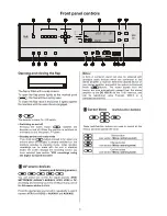
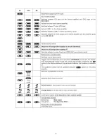
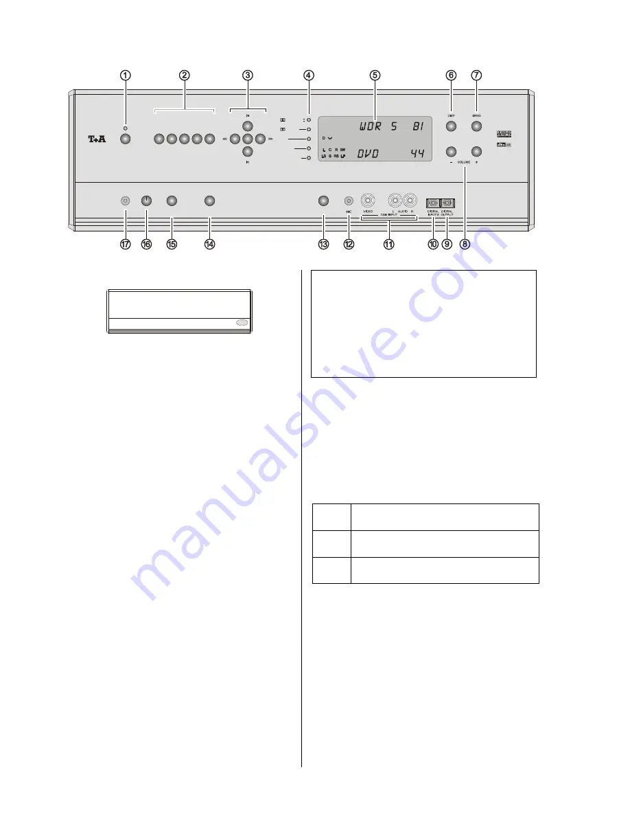
Front panel controls

ON

DVD

STB

AV

VCR

TV

DD 1535 R

AMP

MENU

REC

PHONES

CAM

OK

       DIGITAL

       PRO LOGIC II

x

DTS

OTHERS

SOUNDFIELD

Opening and closing the flap

The flap is fitted with a snap closure.

To  open  the  flap  press  lightly  at  the  marked  point
(

); the flap will then


spring open.

To close the flap raise it and press it lightly against
the machine until


the snap closure engages.


The decoder’s mains On / Off switch.


Switching on and off

Pressing  the  mains  button 

  switches  the

decoder on and off. When the machine is switched on
and ready to use, the green LED glows.


Standby and record ready mode

If you hold the 

 button pressed in for about one

second  when  the  decoder  is  already  switched  on,  the
machine  switches  to  stand-by  mode.  Video  recorder
recordings  can  be  made  with  the  unit  in  stand-by
mode;  the  screen  displays  the  recording  source  you
have  selected  (see  section 

'VCR  recordings  using

the digital surround decoder'

).


AV source devices

(viewing and listening source)


You  can  select  one  of  the  AV  signal  sources  (

DVD

,

SETTOPBOX

AUX/AV1

AUX/AV2

VCR1

VCR2

 or 

TV

)

as viewing and listening source by briefly pressing one of
the 

AV source device

 buttons.

Press the appropriate source button repeatedly to switch
between 

VCR1

 and 

VCR2 

or 

AUX/AV1

 and 

AUX/AV2

.

Notes:

A  form  of  surround  sound  can  also  be  obtained  with
analogue  audio  devices  which  are  connected  to  the
stereo amplifier or receiver. Select the desired device on
your stereo amplifier, and switch the system to Surround
mode  (

-button).  The  sound  signals  from  the

source  are  now  automatically  passed  from  the  stereo
amplifier  to  the 

DD 1535 R

  via  the  TASI  interface,  and

can  be  reproduced  using  ProLogic,  NEO:6  or  a
simulated sound field..


Cursor block

(multi-function buttons)

 

 

These  multi-function  buttons  are  used  to  control  all  the
menus, and also operate the tuner.


Select button

(see section 

'

Menu control system

'

)


Change button

(see section

 '

Menu control system

')

Confirm button

(see section 

'

Menu control system

')

Summary of Contents for DD 1535 R

Page 1: ...V 1 3 Order No 9103 0321 OPERATING INSTRUCTIONS DD 1535 R...

Page 2: ...digital surround decoder This design philosophy includes an insistence on durability and reliability the avoidance of materials which are environmentally harmful the use of metals instead of plastics...

Page 3: ...he first time 35 Wiring diagrams 1 Connecting the decoder to a pre amplifier 38 2 Video monitor with additional Component input 41 3 Connecting a DVD CD player digital picture source 42 4 Connecting a...

Page 4: ...ordings using the digital surround decoder AV source devices viewing and listening source You can select one of the AV signal sources DVD SETTOPBOX AUX AV1 AUX AV2 VCR1 VCR2 or TV as viewing and liste...

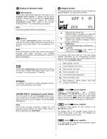
Page 5: ...Mono 2 and Disco see Main Menu Integral screen The display elements of the digital surround decoder are grouped together in a clearly laid out screen a Alpha numeric display field Context sensitive me...

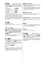
Page 6: ...volume control every time you press one of the volume buttons the volume increases or decreases by 1 5 dB If you hold one of the volume buttons pressed in for longer than a second the volume continues...

Page 7: ...ate high quality headphone amplifier independent of the loudspeaker output stages Note If the loudspeakers are switched on the headphones always supply a STEREO signal regardless of the selected mode...

Page 8: ...d to Hi Fi mode The decoder receives its remote control commands via the RLINK master device Press the button to switch it on it switches itself off when the Master device is turned off In the drawing...

Page 9: ...E AMP mode stereo mode Brief press in surround mode Switches over to stereo mode Toggles volume dependent tone correction LOUDNESS on and off The display area of the decoder always shows the current s...

Page 10: ...is connected to the decoder all the menus are displayed page by page on the television screen at the same time they are displayed line by line on the decoder s integral screen The following table sho...

Page 11: ...surround loudspeakers 5 1 mode Stereo Even if a multi channel signal is detected the decoder converts it into a stereo signal i e all channel information is mixed down and sent to the main left and r...

Page 12: ...zz club with a pattern of reflections dominated by large floor and wall surfaces Also good for simulating small halls Church Simulation of the acoustic conditions in a large church with long reverbera...

Page 13: ...ear and center This task is carried out in the Speaker Balance Setup Dynamic range The dynamic range is the difference in volume between the quietest and loudest passages of a recording The original s...

Page 14: ...14...

Page 15: ...y match each other perfectly and at the same time set them to suit the acoustic characteristics of your listening room This procedure only needs to be carried out when you are installing the system or...

Page 16: ...n but not on the TV screen on The Main Menu appears on the TV screen and also line by line on the decoder s screen On screen language The on screen menus can be displayed on the TV screen in different...

Page 17: ...You can also select at this point whether the surround channels of 5 1 input signals are only to be reproduced by the surround loudspeakers or by the back loud speakers or both see Speaker size menu...

Page 18: ...center speaker Select one of the following settings none if no center loudspeaker is present The center channel is mixed down onto the left and right main loudspeakers Satellit for small centre loudsp...

Page 19: ...he menu point Surround loudspeakers the back loudspeakers are automatically switched off Not all combinations can be set this is deliberate in order to avoid senseless settings 5 1 Surnd LS As describ...

Page 20: ...eproduced by the sub woofer For constant sub woofer operation the low pass filter on the sub woofer must be switched on and the transition frequency on the sub woofer set in such a way that the sub wo...

Page 21: ...een the listening position and the loudspeakers in your surround system and enter the measured distances Note The maximum distance of a loudspeaker to the listening position is 12 m For acoustic reaso...

Page 22: ...As the illustration shows the hiss is reproduced on all the channels in turn in each case lasting about two seconds When the hiss is sounding on a particular channel the on screen menu indicates the...

Page 23: ...controls Make sure that the sound source you choose is active on all the channels so that the sound image is typical of your listening habits and any changes you make to the tone controls are immedia...

Page 24: ...The DD 1535 R now carries out the automatic calibration process During the procedure you will hear your loudspeakers emit various test signals During the period of the calibration procedure it is imp...

Page 25: ...the Video Inputs menu you determine for each AV input whether the source device connected to it is to operate in normal Video or S Video mode Notes If your device features S Video outputs we recommen...

Page 26: ...mal video signals Video or S Video of this source through to the corresponding MONITOR output At the same time the YUV signals of the source are passed to the YUV monitor output You can then switch be...

Page 27: ...vailable alternative inputs of the DD 1535 R the co axial and optical digital inputs DIG 1 DIG 2 DIG 3 DIG 4 DIG 5 DIG 6 and the multi channel input MCH IN Each of these alternative inputs can be assi...

Page 28: ...ilities and how they can be implemented please ask your local specialist dealer or an experienced electrician Audio delay for all sources The basic sound delay setting LipSync is crucially dependent u...

Page 29: ...es This section describes all those matters which are of fundamental importance when setting up and first using the equipment This information is not relevant in daily use but you should nevertheless...

Page 30: ...necting a active center loudspeaker PRE OUT SC LINK Output for connecting a active sub woofer with SC LINK input PRE OUT SUBWOOFER 2 sockets for active sub woofers CINCH TASI Interface for connecting...

Page 31: ...ack stoppers can be removed from the loudspeaker terminals The speakers can then be connected using banana plugs The stoppers are simply a push fit in the terminals and can be prised out from the rear...

Page 32: ...connected to the projector in addition in order to provide a video connection Available as an option YUV converter module The YUV converter module converts all Video and S Video input signals to YUV...

Page 33: ...e machine remain connected to the mains power supply If the decoder is not to be used for a long period we recommend that you isolate it from the mains by pulling out the mains plug at the wall socket...

Page 34: ...part of our conformity declaration and therefore of the approval for operation of the device The serial numbers on the decoder and in the original documentation supplied with it in particular the ins...

Page 35: ...e that they do not compromise the stability of the unit The unit should be set up in a dry well ventilated site out of direct sunlight and away from radiators The unit must not be located close to hea...

Page 36: ...ains lead in conjunction with the POWER BAR mains distribution panel which is fitted with a phase indicator as standard As the decoder can be combined with a very wide range of different AV components...

Page 37: ...he monitor socket on the decoder to your TV set using a video cable Note If your TV set has a SCART input socket please use the S Video SCART adaptor lead supplied Connect the aerial input FM ANT to a...

Page 38: ...ifier using the TASI lead Connect the RLINK socket on the decoder to the RLINK socket on the integrated amplifier Please be sure to connect the pre amplifier output PRE on the pre amplifier to the sub...

Page 39: ...Wiring diagram 1 Connecting the loudspeakers and the TV set to the DD 1535 R Use of banana plugs see the section entitled Back panel connections 5 1 Loudspeakerset 6 1 Loudspeakerset 7 1 Loudspeakers...

Page 40: ...40...

Page 41: ...r high quality picture reproduction select the YUV input on your projector when using DVD this may have to be done manually if your projector does not feature automatic input signal detection 2 S Vide...

Page 42: ...DVD sound inputs of the DD 1535 R If you also wish to use the DVD player as a high quality CD player connect its analogue output to the pre amplifier input CD Connect the die S Video OUT socket of yo...

Page 43: ...een DVD player and stereo amplifier only necessary if the DVD is also to be used for pure two channel stereo reproduction via the stereo amplifier or if you wish to use an audio recorder TAPE to make...

Page 44: ...44...

Page 45: ...45 Wiring Diagram 4 a DVD player with YUV Component Video output connected to the DD 1535 R...

Page 46: ...n also be connected to the SETTOPBOX input in the same manner If the set top box only features SCART connections please use a SCART S Video adaptor cable to connect the system components Finally conne...

Page 47: ...47 Wiring Diagram 5...

Page 48: ...rd from sources whose analogue sound outputs are connected to the DD 1535 R If you are using a device with a digital sound output please be sure to connect the analogue sound output to the input socke...

Page 49: ...e of accessories includes the specially shielded POWER FOUR mains lead the POWER LINE mains lead with sleeve core filters and the POWER BAR multiple socket outlet with mains filters In many instances...

Page 50: ...screen itself A further point is that exotic sound effects have been in use in the cinema since the 1950 s using proper multi channel sound systems These effects are often crucial to the overall impa...

Page 51: ...e g Dolby Surround encoded source material This interface is the key to integrating the decoder elegantly into the overall system At the same time the decoder has absolutely no effect on normal stere...

Page 52: ...tilises five separate sound channels three front channels left centre right and two surround channels A sixth independent bass effect channel is also present catering for low frequency effects LFE Tha...

Page 53: ...d process The surround loudspeakers are supplemented by back speakers in a similar way to Dolby Digital EX The sound signal is produced during the decoding process from the surround channels by means...

Page 54: ...rs without echo or delay The strongly concentrated sound produced in this way generates an immediate energy charged atmosphere which is a great choice for any party Note With the Dolby Digital EX DTS...

Page 55: ...channel reaches the associated ear of the listener but not the opposite ear Furthermore the reflections in the room and the shoulder area of the listener simply do not occur The result of this is tha...

Page 56: ...CVBS S Video also known as Y C or S VHS and Component Video common abbreviations YUV Y Pb Pr or Y Cb Cr Video is supported by virtually all source devices TV sets monitors and video recorders It is th...

Page 57: ...4 and the chapter Configuration YUV Inputs Note Even if you own YUV capable source devices you still need to connect standard Video or S Video cables as these signals are essential for video recordin...

Page 58: ...cedure described above Remote control handset Hold the button and the numeric button pressed in simultaneously After about ten seconds the LED starts to flash Now press the numeric button or Pressing...

Page 59: ...OUND or one of the sound fields Cause 4 Programme contains no information on the auxiliary channels e g stereo material Remedy If you wish call up the Main Menu and select a sound field Cause 5 The le...

Page 60: ...matic PAL NTSC format switching or use the surround receiver s integral screen Problem Picture correct but no sound audible through the decoder Cause 1 No sound connection between source device and de...

Page 61: ...ist shops for connecting a SCART socket to other standard connectors Cinch or Hosiden STANDBY The digital surround decoder can be switched on from stand by mode at any time by pressing a button on the...

Page 62: ...62...

Page 63: ...S N 106 dB Pre amplifier Freq response 1 Hz 400 kHz THD 0 002 S N A 107 dB Volume control type Analog Step 1 5 dB Power amplifiers No 5 Nom output channel 4 8 150 110 Peak output channel 4 8 250 170 D...

Page 64: ...elektroakustik GmbH Co KG Herford Deutschland Germany...

Reviews: