46
Digital SAT receiver (set-top box)
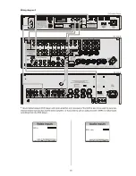
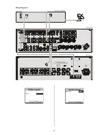
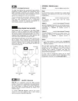
The components of your system should be connected as
shown in Wiring Diagram 5. This is the procedure:
•
If the set-top box features an optical digital sound
output,
connect
it
to
the
digital
input
(
DIGITAL INPUT 1
or
2
) of the
DD 1535 R
using an
optical cable.
Note:
Set-top boxes with a co-axial digital output can be
connected to one of the (Cinch) digital inputs
3 . . . 5.
•
Use an
S-Video
cable to connect the
S-Video
soc-
kets on the set-top box to the
S-Video
input sockets
of the
DD 1535 R
.
Note:
Instead of a set-top box, any other AV source device
can also be connected to the
SETTOPBOX
input in
the same manner.
If the set-top box only features SCART connections,
please use a SCART / S-Video adaptor cable to
connect the system components.
•
Finally connect the equipment to the mains supply
and switch the system on.
•
Settings in the
'
Inputs Menu
'
:
The digital sound signal of the
set-topbox
is
connected to the optical digital input
DIG-1
on the
SR 1535 R
; to cater for this you should add the name
STB
as a suffix to
DIG-1.
•
In the
'
Video Input menu
'
select the type of video
signal (in this case S-Video) for the appropriate input.
Selecting the source device settopbox in normal use:
•
The source button
on the front panel or the
remote control button of the same name selects the
settopbox
as current
surround viewing and
listening source
.
Summary of Contents for DD 1535 R
Page 1: ...V 1 3 Order No 9103 0321 OPERATING INSTRUCTIONS DD 1535 R...
Page 14: ...14...
Page 40: ...40...
Page 44: ...44...
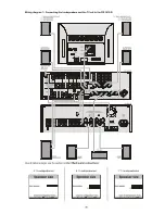
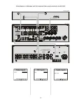
Page 45: ...45 Wiring Diagram 4 a DVD player with YUV Component Video output connected to the DD 1535 R...
Page 47: ...47 Wiring Diagram 5...
Page 62: ...62...
Page 64: ...elektroakustik GmbH Co KG Herford Deutschland Germany...


