51
The
surround system
Multi-channel
reproduction
based
on
surround
technology does indeed open up new worlds of
experience, but the technical implementation of a multi-
channel surround system does involve a number of
potential pitfalls. Many existing surround systems have
gained a reputation for no more than moderate sound
quality, especially when used in normal stereo mode.
The reason for this lies in the tiny magnitude of the
sensitive analogue stereo signals. These signals are
measured in the range of just a few Millivolts
(thousandths of a Volt), and unwanted interference to
these signals can be perceived by the human ear even
when a thousand times smaller than that. Conventional
surround amplifiers feature a single case in which digital
signals and high-frequency video signals live in the same
space as the sensitive analogue signals, and this
represents an open invitation for interference between
the various signals.
This compromise solution is entirely unacceptable to us
at
, so for our surround system we developed an
arrangement in which the various signal processing
sections were kept entirely apart. The system therefore
comprises two specialised devices: an analogue two-
channel stereo amplifier is used to process high-quality
stereo signals, while the digital surround signals are
processed in the surround decoder which is an
independent machine.
In the
system the analogue and digital sub-
assemblies are separated from each other completely,
and this eliminates the danger of interference to the
delicate analogue signals. The net result is that there is
absolutely no danger of a loss in quality in analogue
stereo reproduction.
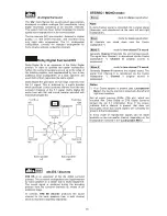
To make it possible to integrate the surround decoder
easily into an existing
system, we developed the
surround interface (TASI), which also provides the
means to process and reproduce analogue signals, e. g.
Dolby Surround encoded source material.
This interface is the key to integrating the decoder
elegantly into the overall system. At the same time the
decoder has absolutely no effect on normal stereo
signals, since it is completely removed from the signal
path during normal stereo operations.
Not even the length of the signal paths is changed; in
stereo mode all signals remain in the pre-amplifier
section of the amplifier, i. e. they are not forced to make
a detour through the surround decoder.
When the system is used in Pro Logic II mode, the TASI
interface also ensures that the decoder is looped in at
the ideal point and at the optimum level in terms of signal
processing, i. e. directly after the source selector switch.
An additional advantage of the TASI interface is that it
makes it possible to exploit the superb output stages of a
typical
stereo system for the front channels when in
surround mode.
To ensure that the sound from the whole system is as
balanced and harmonious as possible, the output stages
built into the decoder are identical in circuit design to our
stereo output stages. This design philosophy ensures
identical frequency, phase and transient behaviour on all
channels, combined with perfectly balanced dynamic
characteristics.
The
surround philosophy also provides further
advantages: two separate pre-amplifier circuits are
present, each with its own volume and tone control
functions: a stereo pre-amplifier and an independent six-
channel pre-amplifier in the surround decoder.
It is therefore possible to adjust the levels and tone
settings separately to meet the different requirements for
stereo and surround modes. When you switch mode, the
correct settings automatically take effect.
TASI
An
alo
gu
e S
te
re
o
DECODER
D
ig
ita
l S
urr
ou
nd
ProLogic
Front
Sub In
Sub Out
A
na
lo
gu
e S
te
re
o
Vid
eo
MCH Out
STEREO
OUTPUT STAGE
FRONT
LEFT
FRONT
RIGHT
REAR
LEFT
CENTER
REAR
RIGHT
SUBWOOFER
ACTIV
TV
3-CHANNEL
OUTPUT STAGE
STEREO
OUTPUT STAGE
BACK
LEFT
BACK
RIGHT
DOLBY DIGITAL EX /
DTS ES VERSION
Summary of Contents for DD 1535 R
Page 1: ...V 1 3 Order No 9103 0321 OPERATING INSTRUCTIONS DD 1535 R...
Page 14: ...14...
Page 40: ...40...
Page 44: ...44...
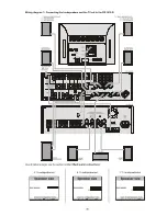
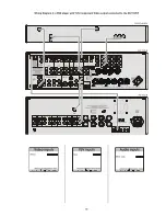
Page 45: ...45 Wiring Diagram 4 a DVD player with YUV Component Video output connected to the DD 1535 R...
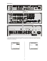
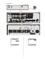
Page 47: ...47 Wiring Diagram 5...
Page 62: ...62...
Page 64: ...elektroakustik GmbH Co KG Herford Deutschland Germany...


