58
Trouble-shooting
Many problems have a simple cause and a
correspondingly simple solution. The following section
describes a few difficulties you may encounter, and the
measures you need to take to cure them.
If you find it impossible to solve a problem with the help of
these notes please disconnect the unit from the mains and
ask your authorised
specialist dealer for advice.
Service Menu
The operation of the service menu is similar to the
operation of the setup menu (see chapter
'
Menu control
system
'
).
Display Service Menu
First display the software version number:
•
Switch on the machine.
•
Wait until the screen displays the loudspeaker
symbols.
•
Hold the
button on the front panel pressed in
(approx. 2 seconds).
•
The software version number
'
Vx-xx
Vx-xx
Vx-xx
Vx-xx
'
and the DSP
version number
'
xxx
xxx
xxx
xxx
'
of the machine are now displayed
on the integral screen.
•
When the software version has been displayed, hold
the
button on the front panel pressed in. The
integral screen now shows the message
'
-----
-----
-----
-----
'
, and the
TV screen displays the
'
Service-Menu
'
.
In the
'
Service-Menu
'
the following items can be
adjusted:
-
Reset to factory default settings
Choose
'
RESET
RESET
RESET
RESET YES
YES
YES
YES
'
and then press the
button
and keep it pressed for a couple of seconds.
-
Selection of the video standard. Choose between PAL
and NTSC according to the requirements of qour TV set.
-
The menu item
'BACK'
should always be set to
'
BACK
BACK
BACK
BACK
'
.
The
'
Zo-2
Zo-2
Zo-2
Zo-2
'
setting is only for service tests.
Switching the remote control address
DD 1535 R:
Proceed as described above (see chapter
'
Service-
Menu
'
until the software version is desplayed.
While the version no. Is displayed on the VFD display
press the
button until
RC-ADR 1
or
RC-ADR 2
is
displayed. This switches the machine to the displayed
address.
To switch back to the previous address, switch the
machine off and repeat the procedure described above.
Remote control handset:
Hold the
button and the numeric button
pressed in simultaneously. After about ten seconds the
LED starts to flash. Now press the numeric button
or
.
Pressing the numeric button
sets the remote
control system to the normal address (
RC-ADR 1)
,
whereas numeric button
sets the alternative
address (
RC-ADR 2)
.
The LED goes out to confirm that
the switch has taken place.
Problem:
Machine does not switch on (green
LED does not light up).
Cause:
Mains lead not plugged in correctly.
Remedy:
Check connections, push plugs in firmly.
Problem:
Machine does not respond when
buttons are pressed.
Cause:
Static discharge or powerful interference
(e. g. lightning) have corrupted the
processor memory.
Remedy:
Reset machine
: disconnect mains plug,
wait about 10 seconds and re-connect.
Switch unit on again.
Problem:
The menu control system does not
work.
Cause:
Master unit software is not designed for
decoder operation.
Remedy:
Software update required in master
machine; ask your specialist
dealer.
Problem:
Machine
responds
correctly
to
manual operation of the buttons, but
does not respond to remote control
commands via the 'R'-series pre-
amplifier, integrated amplifier or
receiver.
Cause 1:
Incorrectly inserted batteries or flat
batteries in the remote control handset.
Remedy:
Re-install batteries correctly or fit new
ones.
Cause 2:
Remote control handset set to the wrong
address.
Remedy:
Set the correct remote control address
on the handset (see chapter
'
Switching
the remote control address
'
).
Cause 3:
No visual contact between remote
control transmitter and remote control
receiver attached to the
'R'
-series pre-
amplifier,
integrated
amplifier
or
receiver.
Remedy:
Ensure
direct
line-of-sight
contact
between remote control transmitter and
receiver. Note that glass doors may
prevent the system working properly.
Maximum range between transmitter
and receiver approx. 8 metres.
Position the receiver in such a way that
it is not subjected to direct sunlight or
strong artificial lighting. Fluorescent and
energy-saving
lamps
are
powerful
sources of interference.
Summary of Contents for DD 1535 R
Page 1: ...V 1 3 Order No 9103 0321 OPERATING INSTRUCTIONS DD 1535 R...
Page 14: ...14...
Page 40: ...40...
Page 44: ...44...
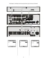
Page 45: ...45 Wiring Diagram 4 a DVD player with YUV Component Video output connected to the DD 1535 R...
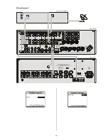
Page 47: ...47 Wiring Diagram 5...
Page 62: ...62...
Page 64: ...elektroakustik GmbH Co KG Herford Deutschland Germany...


