20
Back panel connections
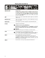
ANALOG OUT
Analogue output
The output sockets should be connected to the appropriate input sockets of the
pre-amplifier, integrated amplifier or receiver in accordance with their markings
(L / R). Select the input sockets of the amplifier or receiver which correspond to
the device address set in the
‘Device address’
configuration menu (chapter
‘Basic functions of the
MP 1260 R
’) (in most cases the address AUX1 should
be used for the
MP 1260 R
).
ANT
Space for input sockets of optional add-on modules (applies only to particular
model variants).
DIGITAL OUT
Digital co-axial output for connection to an external digital/analogue converter
with an co-axial cable.
DIGITAL IN
Inputs for digital source devices with optical or coaxial digital audio output.
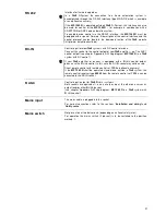
WLAN
Input socket for WLAN antenna
Automatic Activation of the WLAN Module
After powering on the
MP 1260 R
detects if it is connected to a wired LAN
Network. If no wired LAN connection is found, the
MP 1260 R
will automatically
activate its WLAN module and it will try to get access to your WLAN network.
Attention!
When WLAN shall be used, the LAN socket must be left unconnected.
LAN
Socket for connection to a wired LAN (Ethernet) home network.
If a LAN cable is connected this will have priority over wireless WLAN net-
works. The WLAN module of the
MP 1260 R
will automatically be disabled.
USB 1
Socket for USB memory sticks and external hard discs
The storage device must be formatted with a FAT16 or FAT32 filesystem.
The USB device (example 2,5 inch HDD) can be supplied with power from the
MP 1260 R
via the USB socket provided the power consumption of the USB
device conforms to the USB standard.
USB 2
Socket for iPods (use the original lead supplied with the iPod for this)
Summary of Contents for MP1260R
Page 1: ...Software Version V 2 5 Order No 9103 0397 UK USER MANUAL MP 1260 R ...
Page 18: ...18 ...
Page 38: ...38 ...
Page 43: ...43 Anhang Appendix ...
Page 46: ...46 ...
Page 48: ... elektroakustik GmbH Co KG Herford Deutschland Germany ...


