49
Setting up
Carefully unpack the equipment and store the original
packaging in a safe place.
The carton and packing materials have been specially
designed for this series of equipment. They provide a
safe container for the system, and you may need them
for subsequent transport.
Please read through the Safety Notes in these
instructions, and be sure to observe our recom-
mendations relating to location and setting up.
Set up the machines one on top of the other as shown in
the wiring diagrams in the appendix.
Note:
If you prefer to set up the machines on a single level (in-
line arrangement), you will need the
'MQ 820'
mounting
set, which is available as an accessory. This includes the
longer cables required, and sealed case covers without
cable openings.
If you wish to set up the system on a delicate (painted)
surface, check on an unobtrusive area that the equip-
ment’s feet will not damage the surface.
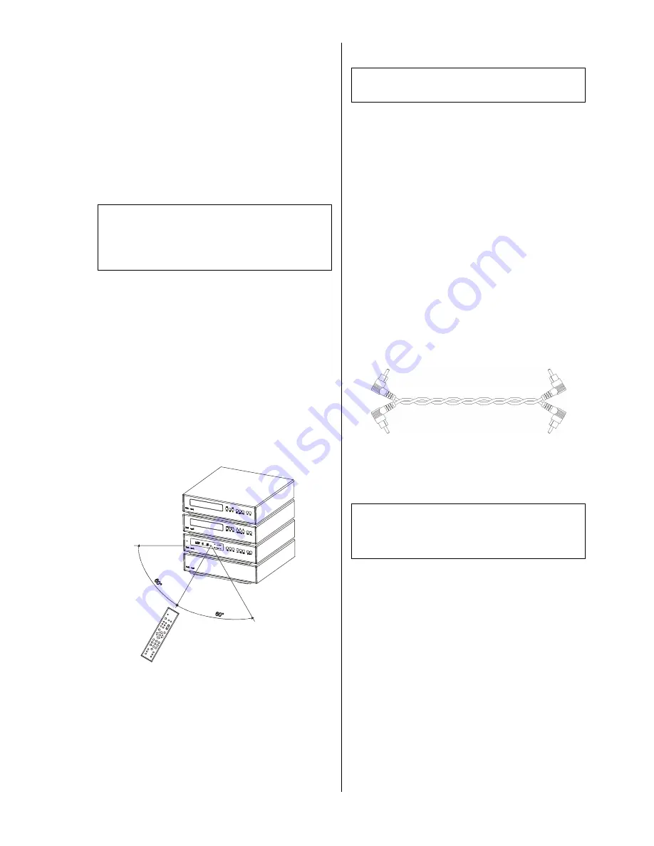
The
remote control receiver
is located within the area
of the integral screen.
For this reason it is important to set up the system so
that there is direct visual contact between the screen and
the remote control transmitter (handset). The maximum
range is 6 metres.
Infra-red reception can be disturbed if lighting levels are
excessive. Energy-saving bulbs and fluorescent tubes
are particularly powerful sources of interference.
The sketch below shows the radius of action of the
remote control system.
If the reception conditions are especially difficult (e. g.
concealed location, or lighting-induced interference, we
recommend the use of the
E 2000
external remote
control receiver.
Wiring
Note:
Disconnect the mains plug at the wall socket before
carrying out any wiring on the system.
Open the back panel flaps by swivelling them upward.
•
For the stereo version of the
M 820
system (i. e. no
DD 820 M
surround decoder), please connect the
equipment as shown in wiring diagram 1a (standard) or
1b (bi-wiring). You will find the wiring diagrams in the
Appendix.
•
For the surround version of the
M 820
system (i. e.
including the
DD 820 M
surround decoder), please
connect the equipment as shown in the wiring diagram
included in the
DD 820 M
operating instructions.
Route the leads running to the upper units in the stack
through the appropriate cover openings in the lower
units.
Mains cables, loudspeaker cables and the
M
LINK
leads
should be kept as far away as possible from signal leads
(Cinch leads) and the aerial cable, to avoid adverse
effects on reproduction quality.
To achieve maximum possible signal : noise ratio we
recommend that you twist together the two Cinch leads
between the
PT 820 M
and the
PA 820 M
as shown in
the drawing below.
The right-angled aerial plug supplied should be used to
connect your aerial system to the
PT 820 M
.
When you have completed all the connections please
close the back panel flaps.
Caution!
Please note that the back panel flaps are spring-loaded,
and close automatically. To avoid trapping your fingers,
close them by holding them from the rear, and not from
the sides.
Summary of Contents for PT 820 M
Page 1: ...V 1 0 Bestell Nr Order No 9103 0289 BETRIEBSANLEITUNG USER MANUAL PA 820 M PT 820 M...
Page 2: ...2...
Page 28: ...28...
Page 29: ...29 English...
Page 54: ...54...
Page 60: ...elektroakustik GmbH Co KG Herford Deutschland Germany...


