background image


34

Safety notes 


All the components in this device fulfil the currently valid German and European 
safety norms and standards. 

We  ensure  that  our  products  are  of  consistently  high  quality,  and  meet  all 
specifications, by checking all materials rigorously for quality, using meticulous 
production  methods  and  subjecting  each  unit  to  a  fully  automatic  computer-
controlled final inspection. 

For  your  own  safety  please  consider  it  essential  to  read  these  operating 
instructions right through, and observe in particular the notes regarding setting 
up, operation and safety. 


Installation 


The  unit  must  be  set  up  in  such  a  way  that  none  of  the  connections  can  be 
touched  directly  (especially  by  children).  Be  sure  to  observe  the  notes  and 
information in the section 

'

Installation and Wiring

'


Loudspeaker connection 
terminals 


The  loudspeaker  terminals  (marked  with  the 

-symbol)  can  carry  high 

voltages.  Touching  the  terminals  or  any  wires  connected  to  them  must  be 
avoided. 


Power supply


The  power  supply  required  for  this  unit  is  printed  on  the  mains  supply  socket. 
The unit must never be connected to a power supply which does not meet these 
specifications.  If  the  unit  is  not  to  be  used  for  a  long  period  disconnect  it  from 
the mains supply at the wall socket. 


Mains leads / Mains plug


Mains leads must be deployed in such a way that there is no danger of damage 
to  them  (e. g.  through  persons  treading  on  them  or  from  furniture).  Take 
particular care with plugs, distribution panels and connections at the device. 

Unplugging the mains plug will disconnect the device from the mains for service 
and repair. Please make sure that the mains plug is easily accessible. 


Enclosure openings 


Liquid  or  particles  must  never  be  allowed  to  get  inside  the  unit  through  the 
ventilation slots. Mains voltage is present inside the unit, and any electric shock 
could  cause  serious  injury  or  death.  Never  exert  undue  force  on  mains 
connectors. 

Protect  the  unit  from  drips  and  splashes  of  water;  never  place  flower  vases  or 
fluid containers on the unit. 


Supervision of device 
operation 


Like  any  other  electrical  appliance  this  device  should  never  be  used  without 
proper supervision. Take care to keep the unit out of the reach of small children. 


Service, Damage 


The  case  should  only  be  opened  by  a  qualified  specialist  technician.  Repairs 
and  fuse  replacements  should  be  entrusted  to  an  authorised 

  specialist 

workshop.  With  the  exception  of  the  connections  and  measures  described  in 
these  instructions,  no  work  of  any  kind  may  be  carried  out  on  the  device  by 
unqualified persons. 

If  the  unit  is  damaged,  or  if  you  suspect  that  it  is  not  functioning  correctly, 
immediately  disconnect  the  mains  plug  at  the  wall  socket,  and  ask  an 
authorised 

 specialist workshop to check it. 


Over voltage 


The  unit  may  be  damaged  by  excess  voltage  in  the  power  supply,  the  mains 
circuit  or  in  aerial  systems,  as  may  occur  during  thunderstorms  (lightning 
strikes) or due to static discharges. 

Special  power  supply  units  and  excess  voltage  protectors  such  as  the 


'Power  Bar'

  mains  distribution  panel  offer  some  degree  of  protection  from 

damage to equipment due to the hazards described above. 

However,  if  you  require  absolute security  from  damage  due  to excess  voltage, 
the only solution is to disconnect the unit from the mains power supply and any 
aerial systems. 

To  avoid  the  risk  of  damage  by  overvoltages  we  recommend  to  disconnect  all 
cables from this device and your HiFi system during thunderstorms. 

All mains power supply and aerial systems to which the unit is connected must 
meet  all  applicable  safety  regulations  and  must  be  installed  by  an  approved 
electrical installer. 




Note: 

Many  insurance  companies  offer  lightning  damage  insurance  for  electrical 
equipment as part of their household insurance service.


Summary of Contents for POWER PLANT MK I

Page 1: ...Software Version V 1 0 Bestellnummer Order No 9103 0418 DE UK BETRIEBSANLEITUNG USER MANUAL E SERIES POWER PLANT MK II...

Page 2: ...2...

Page 3: ...3 Seite page Deutsch 4 English 22 Anhang Appendix A Anschlussbilder 40 Wiring diagrams 40 Anhang Appendix B Technische Daten 43 Technical specifications 43...

Page 4: ...rd auf Metalle oder andere unbedenkliche Materialien zur ckge griffen die einerseits gut recyclebar sind und andererseits eine sehr gute elektrische Abschirmung ergeben Durch unsere massiven Ganzmetal...

Page 5: ...rke und Balance 6 Quellenwahl 7 Klangregelfunktionen 8 Fernbedienung 9 Anschluss und Inbetriebnahme Anschlusselemente 12 Aufstellung und Verkabelung 14 Sicherheitshinweise 16 Sonstiges Betriebsst run...

Page 6: ...as entsprechende Quellger t ber ein E LINK Kabel mit dem Voll verst rker verbunden wird es automatisch mit eingeschaltet Lautst rke und Balance Balance Einstellung Zur stufenlosen Einstellung der Pege...

Page 7: ...n eine laufende Tonband oder CD Aufnahme ab geh rt werden Hinterbandkontrolle Antippen des Monitor Tasters schaltet die Monitor Funktion ein und aus Bei eingeschalteter Monitorfunktion leuchtet die LE...

Page 8: ...zur Verf gung Versenkbare Bedienkn pfe Im Normalfall sind die Kn pfe der Klang und Balanceregelung in der Front versenkt Nach Antippen eines Bedienknopfes f hrt dieser aus der Front heraus und l sst s...

Page 9: ...altetem Vollverst rker wird dieser eingeschaltet und gleichzeitig das betreffende Quellger t selektiert Kein Music Player vorhanden Music Player vorhanden Kurz antippen Lange dr cken Streaming Client...

Page 10: ...10...

Page 11: ...diesem Kapitel werden alle Dinge von grunds tzlicher Bedeutung f r die Aufstellung und Inbetriebnahme beschrieben die nicht f r den t glichen Umgang mit dem Ger t relevant sind die aber trotzdem vor d...

Page 12: ...uf zeichnungs und Wiedergabem glichkeiten Recorder PRE OUT Vorverst rker Ausgang zum Anschluss externer Endstufen oder aktiver Lautsprecher R und L LS Anschlussklemmen Es kann ein Lautsprecher Paar an...

Page 13: ...Ger te mit E LINK Eingang RC IN E 2000 Falls kein Music Player CD Player E Serie in der Anlage vorhanden Anschluss f r E2000 Fernbedienungsempf nger aus Fernbedienungsset FBS100 Netzschalter Mit dem...

Page 14: ...enungs Kabel m glichst entfernt von Ton und Antennenleitungen und keinesfalls ber oder unter dem Ger t Das Anschlussschema des Ger tes ist im Anhang A dargestellt Hinweise zum Anschluss Stecken Sie al...

Page 15: ...en Hilfe sich fast jedes Anschluss und Aufstellungsproblem l sen l sst Netzkabel und Netzfilter ber die Netzstromversorgung gelangt nicht nur die notwendige Betriebs energie zu Ihren Ger ten sondern o...

Page 16: ...ngen d rfen keine Fl ssigkeiten oder Fremdk rper in das Ger t gelangen Im Inneren f hrt das Ger t Netzspannung es besteht die Gefahr eines t dlichen elektrischen Schlages Sch tzen Sie das Ger t vor Tr...

Page 17: ...e den Kontroll und Garantiezertifikaten d rfen nicht entfernt oder ver ndert werden und m ssen bereinstimmen Bei Versto gegen diese Bestimmungen gilt die Konformit tszusage von als widerrufen und ein...

Page 18: ...tzstecker ziehen und nach ca 1 Minute wieder einstecken Ger t ein schalten Ger t reagiert korrekt auf Bedienung ber die Ger te taster l sst sich aber nicht fernbedienen Ursache 1 E LINK Kabel zum Musi...

Page 19: ...besch digte Kabel austauschen Ursache 3 bersteuerung durch schlechten Massekontakt Abhilfe Eingangskabel abziehen und warten ob der Verst rker wieder einschaltet wenn ja dann Eingangskabel berpr fen u...

Page 20: ...der Eingangsstufe des Vorverst rkers mit einer hohen Verst rkung gearbeitet werden kann ohne eine bersteuerung des Vorver st rkers zu riskieren Daf r sorgt der erste Lautst rke Regler Im weiteren Verl...

Page 21: ...werden Von einer Record Quelle bzw Aufnahme Quelle k nnen mit einem Recorder TAPE Aufnahmen gemacht werden Eine Aufnahme Quelle kann nicht fernbedient werden Update Upgrade Dieses Ger t kann bei Bedar...

Page 22: ...lso provide effective electrical screening Our robust all metal cases exclude any possibility of external sources of interference affecting the quality of reproduction From the opposite point of view...

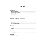
Page 23: ...ion 25 Tone control 26 Remote control handset 27 Using the system for the first time Back panel connections 30 Installation and wiring 32 Safety Notes 34 FCC Information to the user 35 General Trouble...

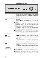
Page 24: ...on using the source buttons If the source device you wish to use is connected to the integrated amplifier via an E LINK cable selecting that source switches on the amplifier automatically Volume and b...

Page 25: ...or function Pressing the Monitor button switches the monitor function on When the monitor function is in operation the LED above this button will glow The tape monitor function only works if the recor...

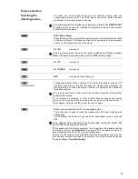
Page 26: ...l use the knobs for tone and balance are recessed into the front panel If you press any of the knobs it projects from the front panel and can then easily be rotated In the centre position the index ma...

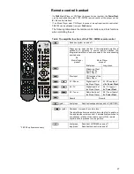
Page 27: ...ource device switches the integrated amplifier on and also selects the corresponding source device No Music Player present Music Player present Brief press Long press Streaming Client function of the...

Page 28: ...28...

Page 29: ...es This section describes all those matters which are of fundamental importance when setting up and first using the equipment This information is not relevant in daily use but you should nevertheless...

Page 30: ...k recorders PRE OUT Pre amplifier output for external power amplifiers or active speakers R und L loudspeaker terminals One pair of loudspeakers can be connected to the amplifier SPEAKER R and SPEAKER...

Page 31: ...ntrol output for devices with E LINK inputs RC IN E 2000 If no Music Player CD Player E Series is present in your system Input socket for E2000 remotre control sensor from the remote control set FBS10...

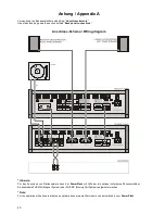
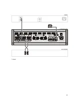
Page 32: ...from signal leads and antenna cables Never run them over or under the unit A complete connection diagram is shown in Appendix A Notes on connections Be sure to push all plugs firmly into their sockets...

Page 33: ...any problem concerning connections and system location Mains cables and mains filters The mains power supply provides the energy which your sound system equipment needs but it also tends to carry inte...

Page 34: ...is present inside the unit and any electric shock could cause serious injury or death Never exert undue force on mains connectors Protect the unit from drips and splashes of water never place flower v...

Page 35: ...sories may be connected to the unit or such auxiliary devices which are themselves approved and fulfil all currently valid legal requirements When used in conjunction with auxiliary devices or as part...

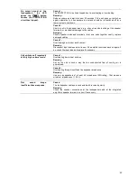
Page 36: ...e connect Switch unit on again Machine responds correctly to manual operation of the buttons but does not respond to remote control commands Cause 1 E LINK cable between Power Plant and Music Player i...

Page 37: ...ed cables Cause 3 Overloading due to poor earth contact Remedy Disconnect input cable and wait to see if the amplifier switches back on again if so check the input lead and replace if necessary Unit s...

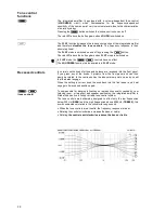
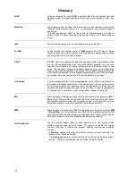
Page 38: ...tre position in any case Loudness A volume dependent tone control Loudness circuit which compensates for the frequency dependent sensitivity of the human ear at very low volume levels At very high vol...

Page 39: ...control The amplifier features a two stage volume control which enables the unit to work at a high level of amplification in the input stage of the pre amplifier without risking overloading the pre a...

Page 40: ...luss Schema Wiring diagram Hinweis F r den Anschluss von Plattenspielern kann der Power Plant mit Hilfe der als optional lieferbaren Phonoverst rker Einbaumodule PHE MM Magnet System oder PHE MC Movin...

Page 41: ...41 optional...

Page 42: ...42...

Page 43: ...gang Kopfh rerausgang Tapeausgang Pre amplifier Headphone Tape record output Netzanschluss PWR requirement 230 V version 115 V version 220 230 V 50 60 Hz 110 115 V 50 60 Hz Leistungsaufnahme Power con...

Page 44: ...elektroakustik GmbH Co KG Herford Deutschland Germany...

Reviews: