background image

66

Configuration

Configuring the Comfort Pro S

Configuring the Comfort Pro S

Preparing the Configuration

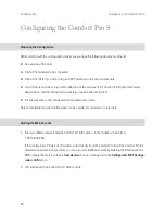
Before starting with the configuration, make sure you have the following documents at hand: 

An overview of the ports

A list of the terminals to be connected 

A list of the IPEIs, if you wish to log on DECT terminals in the secure procedure

A list of the users to be set up (staff entitled to use the services of the Comfort Pro S) with their names, 

departments, and the internal call numbers you want to allocate to them

For Internet access: the Internet service provider access data.

Data not available for initial configuration can be updated or corrected at a later date. 

Starting the Web Console

1.

Start your Web browser. Enter the Comfort Pro S IP address in the “Address” box: http://

192.168.99.254/.

If the configuration PC gets its IP address automatically from the Comfort Pro S or if the Comfort Pro S is 

entered as the domain name server, you can also start the Web console by entering the DNS name. The 

DNS name in the factory setting is 

host.domain

. You can change this in the 

Configurator

 (

NET Configu-

ration: LAN


menu).

2. This will call up the Comfort Pro S’s Web console.

Summary of Contents for Comfort Pro S

Page 1: ...Comfort Pro S Mounting and Commissioning Installation Guide...

Page 2: ......

Page 3: ...tallation 23 Scope of Delivery 24 Safety Precautions 24 Mounting Location 26 Opening and Closing Comfort Pro S 27 Interface Cards 31 Installing Interface Cards 31 Installing a Fax V 24 Card 33 Positio...

Page 4: ...essories 53 Power Supply Unit 53 Key Extensions 54 Headset 56 MountingtheComfortProSRackInfoComSystem 57 Safety Precautions 57 Technical Data 58 Mounting Interface Cards 59 Scope of Delivery 61 Instal...

Page 5: ...and Loading the Configuration 70 Receiving System Messages as E Mail 70 Configuring Fax Boxes 71 Loading SW Updates 72 Resetting the System Data 72 Basic Hardware Settings Switch 73 Factory Settings...

Page 6: ...Link 84 Useful Information on Internet Access 85 Costs 85 Using the Web 85 E Mail 86 NAT 86 VoiceoverIP VoIP 88 Quick Start 89 IP System Telephony 89 External SIP Line 90 Fundamentals 91 Propagation D...

Page 7: ...stem Telephone Configuration 101 LAN DHCP Server 102 Start Procedure 103 Local Configuration 104 Comfort Pro P 300 500 PC 108 Installation 109 Configuration 109 PBXNetworking 111 Connections 111 Proto...

Page 8: ...Numbering 119 Technical Details 119 TeamFunctions 121 Introduction 121 Explanation of Keys 121 Team Configuration 123 Examples of Use 124 Executive Secretary Team 124 Three member Team 126 Unified Tea...

Page 9: ...ring and Managing Companies 138 Assigning Users 138 Assigning Bundles SIP Accounts 139 Allocating Routing Codes 139 Configuring the Company Exchange 140 Working with the Multi Company Variant 140 Comp...

Page 10: ...phony 147 Synchronising the PC Clock 148 Address Queries using LDAP 149 FrequentlyAskedQuestions 150 General Hardware 150 Telephony 151 DECT 154 LAN 155 Internet 156 More Questions 157 TechnicalSpecif...

Page 11: ...s supporting DECT further S0 interfaces or more a b ports can be met by using one or more interface cards without changing the system The operating software is stored on a memory card CompactFlash Thi...

Page 12: ...ropriate combination of two interface cards to 8 S0 connec tions 16 Upn connections or 16 a b connections You will find an overview of the cards available in the section Interface Cards starting on pa...

Page 13: ...he Q SIG network This type of networking is described in the chapter on PBX Networking starting on page 111 DECT Networks Comfort Pro S supports the setting up of a DECT network enabling mobile office...

Page 14: ...can be used to network the communications systems of branch offices instead of ordinary per manent ISDN lines With up to 5 virtual lines the number of calls which can be made simultaneously between tw...

Page 15: ...and these handle the administration of IP addresses and name reso lution for the client computers The Comfort Pro S provides Internet access for all connected PCs through a common IP address Only thi...

Page 16: ...etwork Features You can also offer your staff the option of dialling into the LAN by means of RAS access This type of con nection can also be made using an encrypted Internet data connection VPN Virtu...

Page 17: ...evices The dialling mode IWV or MFV is automatically detected All corded terminals connected to the base module ring if there are incoming external calls The system PIN for remote programmable call di...

Page 18: ...d users in the Online Help in the User Manager chapter The following functions are delivered preset for user groups User group settings Function Authorisation Standard Administrators Guests Applicatio...

Page 19: ...nal s Dial in incoming Pick up from group Pick up selective Call removal Calling suppression at the parallel terminal Reaction connection will be disconnected Call queue 0 0 0 Call forwarding Call for...

Page 20: ...at internal connections Protection Call protection Ringing tone Ringing tone off Call waiting protection Intercom protection Pick up protection Suppress phone number display intern Suppress phone numb...

Page 21: ...locked Program function keys Menu and ABC keys Phone book with menu Preset Disconnect ISP connection Connection data Send incoming connections to COM Send outgoing connections to COM Number of suppre...

Page 22: ...MSN groups can be forwarded Call diversions for other users and call diversions by other users are deactivated The telephone lock can be activated The terminal PIN is 0000 The white list black list a...

Page 23: ...access enables remote users to dial in via VPN PPTP or IPSec or via ISDN with or without call back RAS access requires the activation of the RAS authorisation Multiple e mail account queries can be se...

Page 24: ...Name domain Domain Name Server 192 168 99 254 PPP addresses RAS ISDN 192 168 99 10 to 192 168 99 41 PPTP 192 168 99 50 to 192 168 99 79 IPSEC 192 168 99 90 to 192 168 99 119 DHCP addresses LAN 192 16...

Page 25: ...t assignment Termination Cable Length starting on page 40 6 If available externally connect S0 to NTBA see S0 Ports starting on page 40 7 Plug power cord into power supply unit 8 Close Comfort Pro S s...

Page 26: ...d software Safety Precautions Intended Usage The Comfort Pro S communications system is designed to be connected to ISDN basic rate access multi ter minal access or system access using the Euro ISDN p...

Page 27: ...ric shock The Comfort Pro S does not have its own power supply switch To disconnect the Comfort Pro S from the mains power supply pull the plug out of the power socket Install the Comfort Pro S near a...

Page 28: ...l Area Network Usage Make sure no fluids to get into the Comfort Pro S electric shock or short circuit may result Repairs to the Comfort Pro S and all its accessories and terminals must be carried out...

Page 29: ...ason you should first pick up your tool then touch an earthed metal object e g a radiator before touching any connections or components inside the device Caution Static charges can damage the electron...

Page 30: ...must remove Comfort Pro S s cover completely if you want to install it on a wall or install interface cards 3 Pull the 3 pin AC cable out of the power supply unit 4 Press down the power supply locking...

Page 31: ...from the bottom Taking the cover off To close the Comfort Pro S again follow this procedure in reverse order 7 Put the cover back on 8 Push the cover down as far as the protection plate 9 Lift the st...

Page 32: ...tion Opening and Closing Comfort Pro S Locking in the power supply unit 10 Connect the 3 pin AC cable to the power supply unit Connecting the 3 pin AC cable 11 Push the cover all the way down Close th...

Page 33: ...h interface card is connected to the main board via two sockets Comfort Pro S s large slots have the fol lowing characteristics There is no prescribed order for assignment You can for example use an i...

Page 34: ...ck that it is the correct type of card There is a label specifying the type on the connector Caution Static charges can damage the Comfort Pro S s electronic components so you must provide potential e...

Page 35: ...configured before starting operations Once you have restarted Comfort Pro S you can view the interface cards status in der Web console to do this call up the menu item PBX Configuration Ports Slots Yo...

Page 36: ...e card is sitting firmly in the slot 4 No connections are required for the fax function If you want to use the V 24 function connect the 8 pin RJ45 plug of the provided serial cable with the RJ45 sock...

Page 37: ...of the Comfort Pro S interfaces The following overview shows the interface cards available Interface card Slots Features 1 2 Mini Comfort Pro IF MGC VoIP Media Gateway card Internal connection to the...

Page 38: ...IF S02 UPN6 2 x S0 and 6 x Upn S0 are internally externally switchable Comfort Pro IF S02 UPN6 DECT 2 x S0 and 6 x Upn Upn usable for DECT RFP S0 are internally externally switchable Comfort Pro IF S...

Page 39: ...Upn 1 3 Upn 1 5 Upn 1 6 Upn 1 7 Upn 1 8 Slot 1 Slot 2 Upn 2 1 Upn 2 2 Upn 2 3 Upn 2 4 Upn 2 5 Upn 2 6 Upn 2 7 Upn 2 8 S0 1 1 Slot 1 Slot 2 S0 1 2 Upn 1 1 Upn 1 2 Upn 1 3 Upn 1 4 Upn 1 5 Upn 1 6 S0 2 1...

Page 40: ...and pull the plug out of the mains power supply 2 Take the cover off the Comfort Pro S see Opening and Closing Comfort Pro S starting on page 27 3 Pass the Velcro fastener through the recesses in the...

Page 41: ...ounting recess on the right passing the Velcro fastener over the power supply unit 5 Pass the Velcro fastener through the lug 6 Tighten the Velcro fastener 7 Replace the cover and connect the power ca...

Page 42: ...t the screws through the holes provided The Comfort Pro S will hang on the screws in attachment point A so you must leave a space of 4 mm between the screw heads and the wall Port assignment Terminati...

Page 43: ...nection cable provided For the following example activate the PBX Configuration Ports S0 Line termination option in the Configurator In the NTBA 100 ohms terminating resistors between 1a and 1b as wel...

Page 44: ...Several IAE sockets can be series connected using a bus installation For the following example activate the PBX Configuration Ports S0 Line termination option in the Configurator In the last IAE sock...

Page 45: ...star topology Sub distributions are not allowed either Termination on an IAE socket IAE sockets with built in resistors are recommended because the terminating resistor can be switched on or off with...

Page 46: ...ase station Comfort Pro CB 300 If the DECT base station is connected to a Upn port four calls can be made simultaneously using the handsets If the base station is connected to two Upn ports eight call...

Page 47: ...stem phone or base station cable max 1000 m If you connect a base station to a Upn port four calls can be made simultaneously through this base station using mobile DECT devices 4 x ESC OK 5 8 2 3 6 9...

Page 48: ...mmunication which use pulse dialling or devices which use pulse or DTMF dialling including analogue telephones G3 fax machines analogue modems external devices for Music on Hold external mail systems...

Page 49: ...imum transfer rate for analogue modems is 33 6 kBit s V 34 Music on Hold It is possible to connect a suitable external Music on Hold device If you are not using an external MoH device Comfort Pro S pr...

Page 50: ...ercom system and the DoorLine module should be set to their factory settings In the PBX Configuration Ports a b Change menu in the Configurator select Doorstation 2 wire as the Type Deactivate the Act...

Page 51: ...the Comfort Pro S as an IP router for connection to the Internet among other things Transfer rates and operating modes are switched automatically Auto Sensing function Connections requiring a crossove...

Page 52: ...ily connect a service PC The PoE power supply is automatically deactivated if a device which does not support PoE is connected WAN Port Comfort Pro S can be connected to an external DSL modem and to a...

Page 53: ...terface on the COM port S Please note The connecting cable for the COM port must not be longer than 3 m You can connect a PC to the COM port for transferring call data This call data can then be analy...

Page 54: ...urs the time and date are reset to the factory settings when the power is switched on again Depending on the SYS Configuration System Synchronize Time setting date and time are set to the current valu...

Page 55: ...e Comfort Pro P 300 IP 500 IP system telephone with or without key extension where no Power over LAN is available in the network N Note Use only the power supply unit with the product code 4516000 Con...

Page 56: ...ombination is operating through and the Comfort Pro S must be less than 1000 metres You will need a plug in power supply unit Comfort Pro PN power supply unit product code 4516000 to provide power The...

Page 57: ...phone that is already con nected to Comfort Pro S Pull the telephone plug out of the socket before screwing the key extension onto it IP system telephone with 1 3 key extensions Yes IP system telephon...

Page 58: ...must comply with the DHSG standard connection via RJ45 jack The manufacturers Plantronics and GN Netcom make devices suitable for this purpose Alternatively you can connect a normal headset RJ11 jack...

Page 59: ...sonnel The system needs to be mounted in earthed cabinets or cases Lines and cables connected to the communi cations system must only be laid inside buildings Connecting a b and Upn line outside of bu...

Page 60: ...omfort Pro S N Note The ISDN S0 port S0 ext int on the front panel may only be switched in one di rection internal or external Using the port as internal S0 port requires a crossover Rx Tx patch cable...

Page 61: ...e fields are labelled SLOT 1 and SLOT 2 Depending on the type of interface card used in a slot the correct metal screen has to be mounted Besides the default screen the following screens are available...

Page 62: ...rt Pro S These LEDs are labelled SLOT1 and SLOT2 An LED will show a constant light if an interface card is inserted into the corresponding slot and the operating software has detected an interface car...

Page 63: ...rd starting on page 33 To install the Fax V 24 card perform the following steps 1 Switch off the Comfort Pro S Rack and pull the plug out of the mains power supply Unscrew the screws of the top cover...

Page 64: ...unction connect the 8 pin RJ45 plug of the provided serial cable with the RJ45 socket on the card Connect the other end of the serial cable to the front panel For pull relief fasten the cable with cab...

Page 65: ...ort Pro S Web console Using the Web console you can perform the initial configuration of the Comfort Pro S configure users of the Comfort Pro S and authorise them to use certain system services carry...

Page 66: ...to continue with step 6 2 Windows 2000 XP log on as a user with Administrator rights 3 You will find the IP settings in Windows 2000 XP under Start Settings Network connections Local Area Connection...

Page 67: ...a connected system telephone You can also view the net mask by en tering the procedure 183 The PC s IP address must be in this network range N Note Deactivate any connection via a proxy server which...

Page 68: ...mbers you want to allocate to them For Internet access the Internet service provider access data Data not available for initial configuration can be updated or corrected at a later date Starting the W...

Page 69: ...n enter your user name Administrator password for the initial configuration leave this box blank 4 Confirm this by clicking on OK This puts all connected terminals into the Guest user group with restr...

Page 70: ...input with Apply 7 Click on the Configurator button on the home page You will find notes on using the Configurator and in the online help Click on Help in the menu bar or click on TOC to activate an...

Page 71: ...sole in the Configurator in the NET Configuration LAN menu In the event that the IP configuration of the Comfort Pro S has to be changed and access via the Web console is not possible you can also use...

Page 72: ...tion Configurations are saved in a file archive and can be loaded to the Comfort Pro S either locally from a con nected configuration PC or by remote configuration The following configuration and cust...

Page 73: ...fax box user is automati cally informed of the incoming fax This can be done in various ways In the Telefonie Assistent application for every received fax an entry is added to the Incoming message lis...

Page 74: ...t of the Comfort Pro S software and is automatically loaded into the terminals via the Comfort Pro S For further information refer to the online help documentation under the item SYS Configuration Fir...

Page 75: ...er see Opening and Closing Comfort Pro S Caution Static charges can damage electronic devices Observe the regulations regarding electrostatically sensitive components 3 The basic settings switch is de...

Page 76: ...to the Comfort Pro S Description Setting Comfort Pro S s IP address 192 168 99 254 Comfort Pro S s net mask 255 255 255 0 Comfort Pro S s Host name host Comfort Pro S s Domain name domain DHCP server...

Page 77: ...play time If a larger file is loaded then this will be truncated and thereby will also only be played for 80 seconds The MoH capacity can be subdivided in a maximum of 5 files These files can be used...

Page 78: ...a PC the Comfort Pro S central telephone book and your personal telephone book as well as to the company telephone book if the multi company variant is activated In addition the Comfort Pro S can be u...

Page 79: ...ses in which the first three numbers are the same and the last number is uniquely assigned to a specific device in the LAN On the Internet unique addresses assigned by a special organisation created f...

Page 80: ...information on the names and IP addresses for which it is responsible For all other information a DNS server contacts other DNS servers For the establishment of every connection from the workstation i...

Page 81: ...rk environment These NetBIOS names can differ from the DNS names assigned to the workstations by the Comfort Pro S The Comfort Pro S is not visible in the network environment Internet Access If access...

Page 82: ...et access of the Comfort Pro S As an alternative the ISP trigger call can be configured To secure the data connection the protocols PPTP and IPSEC are available PPTP encryption is optional The necessa...

Page 83: ...sponding IP settings in the Comfort Pro S Configurator NET Configuration LAN menu Additionally you should change the DHCP server to static address assignment in the NET Configuration LAN DHCP Server m...

Page 84: ...u must edit the internal DNS server configuration so that the resolution of external DNS names is forwarded to the Comfort Pro S In this example the Internet connection is established from a workstati...

Page 85: ...SMTP connections If you addi tionally want to allow file or printer access in the network you must set up a suitable user account on the addressed server for network log in If you use the same log in...

Page 86: ...the prescribed address range for the LAN The Comfort Pro S in a LAN to LAN link In the Configurator NET Configuration Branch menu you can configure the dial in settings PPTP The Point to Point Tunnel...

Page 87: ...mitted Unfortunately programs other than those typically intended to access the Internet such as your browser or your e mail software may send out data packets which cause an Internet connection to be...

Page 88: ...example With the Comfort Pro S you can set up one or more e mail accounts for every user account configured on the Comfort Pro S These e mail accounts are then checked at regular intervals If there ar...

Page 89: ...directed connection establishment e g ICQ The protocol will function without TCP UDP port numbers e g ICMP or IGMP The Comfort Pro S NAT has suitable processes for ensuring the functions of many impor...

Page 90: ...t Pro S gives users all the features of system telephony through its use of an IP based protocol Furthermore the standardised SIP protocol can also be used on the intranet The control of the data conn...

Page 91: ...lots Click on the corresponding slot Under Configured select MGC VoIP Optional enter an IP address from the Comfort Pro S IP network which is not being used such as 192 168 99 253 under IP Address Con...

Page 92: ...an IP address under STUN Server and STUN Port where necessary You can obtain more information on this from your SIP provider Click on Apply 5 Click on the existing SIP account on the PBX Configuratio...

Page 93: ...n also be optimised for example by using a modern switch which evaluates the TOS byte of IP packets or by replacing unreliable connections Latency and Packet Length For technical reasons there is alwa...

Page 94: ...onfiguration settings Measuring the network quality may also help The following comparison provides a guide to voice quality with specific quality levels Required bandwidth kilobit s with respect to P...

Page 95: ...The duration of the recording and not the data packet s byte count is relevant in making this selection Duration 30 ms optimal transmission Duration 40 60 ms one quality level depreciation Duration 60...

Page 96: ...propagation delay If this is the case use a modern switch component Selective forwarding of ethernet packets Layer 2 switching avoids collisions Modern switch components also evaluate the TOS byte of...

Page 97: ...hanged between the IP telephone and the gateway t Switching between voice data channels may cause a slight delay in some circum stances For example when accepting a call on an IP telephone headset use...

Page 98: ...ns possible Software MGW The system software for Comfort Pro S provides a Media Gateway function Depending on the system proc essor utilisation and available system memory up to 32 MGW additional chan...

Page 99: ...re stored in its Flash memory The software is updated automatically with a system software Information on Use The MGW interface card must be correctly inserted and configured see also Interface Cards...

Page 100: ...operates a gateway to the ordinary telephone network which users pay to use and which enables the SIP provider to provide calls to the telephone network A SIP connection can also accept incoming calls...

Page 101: ...lated to a valid IP address using address translation NAT Network Address Translation but no status information is available for NAT on an incoming RTP connection To avoid this problem the IP address...

Page 102: ...00 IP and Comfort Pro P 500 IP offer the same features as the corresponding system telephones Using VoIP system telephones is therefore not much different from using standard system telephones The fol...

Page 103: ...Comfort Pro P 300 IP and Comfort Pro P 500 IP obtain the required IP address configuration and operating software via the DHCP BOOTP and TFTP IP protocols After the power supply is assured the device...

Page 104: ...IP system telephone You will find more details in your DHCP service programme s online help or hand book The MAC address of all VoIP system telephones always begins with 00 30 42 2 Configure a fixed I...

Page 105: ...rocedure In this case system software matching the type of VoIP system telephone must be transferred via TFTP The file name is determined by the telephone type After the VoIP system telephone has been...

Page 106: ...ng port number 8101 and sends a registration analogue to the Upn system telephones 7 Extra connections are created using the IP protocol RTP Realtime Transport Protocol for call data when a call is cr...

Page 107: ...duct CD Start Windows Explorer Nav igate to the Product CD Double click the Telekom IpPhoneConfigurator jar file The IP Phone Configurator dialogue opens Select the desired language setting English or...

Page 108: ...the currently shown configuration to the VoIP system telephone The status bar at the bottom edge of the programme window displays send OK N Note The VoIP system telephone receives the configuration a...

Page 109: ...r monitoring purposes VoIP system telephone messages can be sent to a Syslog server Activate the yes option and configure the SYSLOGD IP address and SYSLOGD port settings to activate this function VLA...

Page 110: ...Pro P 500 PC with one key extension As well as VoIP system telephony from workstation computers the Comfort Pro P 300 500 PC includes the following features Usage via Mouse PC keyboard Drag Drop call...

Page 111: ...rom the Comfort Pro P 300 500 PC product CD and follow the installation assistant s instructions Configuration Analogue to the VoIP system telephones the Comfort Pro P 300 500 PC creates multiple IP c...

Page 112: ...e LAN for the device ID Select a random device ID to secure telephone usage The device ID can only be read on the Web console The displayed menu texts and parts of the operations software are elements...

Page 113: ...ics in the Comfort Pro S online help You can use ISDN point to point connections Q SIG or DSS1 protocol or IP connections Q SIG IP protocol for TK system networking N Note If you do not need the featu...

Page 114: ...ISDN can be used Certain PBX networking features can only be used with the Q SIG Q SIG IP protocol however In particular the identifier indicating whether a call is internal or external cannot be tran...

Page 115: ...ork to communicate with each other they must be clock aligned The L1 protocol master sets the clock for layer 1 and the L1 protocol slave adopts synchronises to this clock When planning a PBX networki...

Page 116: ...s There are different types of connection available for an point to point connection between two PBXs depending on the distance between them Direct Connection This type of ISDN point to point connecti...

Page 117: ...an active transmission system can increase the range to up to 50 km Normally the L1 master is the transmission system for the two connected PBXs For the protocol layers L2 and L3 one PBX is normally t...

Page 118: ...f the internet connection and the compression method used A multiple S2M point to point connection is simulated for each Q SIG IP bundle This means that 5 virtual D channels and up to 120 voice channe...

Page 119: ...cannot be operated using a connection with NAT For a Q SIG IP con nection a branch connection or another VPN connection is required Configuration The possible configurations described below can be set...

Page 120: ...the following order PBX 1 first searches for a free channel in the C trunk group If all the lines in trunk group C are busy the system tries to set up a connection via trunk group E PBX 3 switches the...

Page 121: ...entry in the numbering table makes it possible to seize a default route for all remaining unas signed numbers In particular this simplifies configuration of the Comfort Pro S as a subsidiary system t...

Page 122: ...or seizing a route with open numbering are not transmitted to the destination PBX and thus cannot be evaluated by it To reseize a route for example for a callback you must set the appro priate digit p...

Page 123: ...0 500 telephones Depending on the terminal different numbers of call keys are available N Note Only one function or call number can be programmed for each call key Number of available call keys System...

Page 124: ...That team member can take this call by pressing the busy key which seizes his own terminal s trunk key Calls taken via the busy key are not entered in the call list of the team member who was original...

Page 125: ...gh by simply pressing the key Direct call keys for example can be configured at a terminal in a conference room to call the secretary Team Configuration You can create teams and programme call keys in...

Page 126: ...he executive secretary team comprises two members the executive and the secretary The secretary has one Comfort Pro P 300 system telephone and the executive has two one of which is used as a parallel...

Page 127: ...nal since no appropriate trunk key is configured on the latter s telephone Call Signalling In this configuration example calls to one s own call number are signalled acoustically on the following tele...

Page 128: ...d as a trunk key on his tele phone On the other telephones in the team this call number is programmed as a team key e g TK 10 on Johnson s and Smith s telephones The team members can thus see which nu...

Page 129: ...al the team key LED flashes Unified Team The unified team described here is an example of a team configuration within a department in which calls are to be managed quickly e g support department Each...

Page 130: ...am member then presses trunk key TrK 11 on his telephone he can accept the call For further information on function keys refer to the Comfort Pro P 100 300 500 user guide Line Busy Indication If a lin...

Page 131: ...K 15 on Miller s telephone as TK 10 and TK 15 on Johnson s telephone The assumption here is that most calls will go to the respective first call numbers and team members can thus help each other out b...

Page 132: ...he R key For more information refer to the chapter entitled Consultation Toggling Transfer and Conference in the Comfort Pro P 100 300 500 user guide Line Busy Indication If a line is busy e g TrK 10...

Page 133: ...lled by a brief tone in the loudspeaker and in the display If calls are in the queue a number at the beginning of the second line of the display on the Comfort Pro P 500indicates how full the queue is...

Page 134: ...tion Call Distribution Incoming PTP menu Central welcoming texts can be recorded using the programme package Comfort Pro A IAB integrated answering machine You should configure a new user group e g Op...

Page 135: ...for an Operator with Two System Telephones The operator switches all incoming calls and can either work on the Comfort Pro P 500 or the mobile ter minal the Comfort Pro CM 300 Configuration Configure...

Page 136: ...rs do not get a busy signal The display on the Comfort Pro P 500 indicates how many calls there are in the queue If the operator wants to leave the workstation and take along the enquiry station call...

Page 137: ...hone number of the trunk key of their system telephone Activate Call wait prot call waiting protection on all three terminals in the Protection menu Programme a feature key with the function Sign on s...

Page 138: ...possible to configure the Comfort Pro S for each company and define the extent to which the features of the system may be used In brief the features of the multi company variant are as follows Up to...

Page 139: ...e corresponding company or its staff correctly the existing bundles must be uniquely assigned to the companies see Assigning Bundles SIP Accounts starting on page 139 5 In the case of outgoing externa...

Page 140: ...mple the respective configuration is changed to the default company The name of the default company can be changed but the default company itself cannot be deleted Assigning Users For each user you mu...

Page 141: ...f their company s bundle SIP account the assignment of the bundle to the company is irrelevant the charges are assigned according to the source principle Charges are billed to the company to which the...

Page 142: ...es of the Comfort Pro S which the users may already be familiar with from the single company variant are available in the multi company variant These features can be used to the same extent and can be...

Page 143: ...ks This authorisation is useful if members of this group e g the Administrators service the entire system Foreign telephone books can only be edited in the Configurator in the Phone Book menu The numb...

Page 144: ...s for various options that are available are given below Setting up TAPI With a TAPI Telephony Application Programming Interface you can operate a CTI application Computer Telephony Integration Here t...

Page 145: ...e name for the connection In the CTI server box you must enter the DNS name or the IP address of the Comfort Pro S Using the button you can search for this in the LAN In the boxes Username and Passwor...

Page 146: ...CAPI the Comfort Pro S allows the use of ISDN functions also by PCs in which no ISDN card is integrated Requirements You require an active IP network connection between the PC and the telephone system...

Page 147: ...ormation on the working of the NET CAPI driver and CAPI application programmes on the product CD Note on Sending Faxes The NET CAPI can address Group 4 digital ISDN fax receivers but it does not addre...

Page 148: ...up the config uration dialogue Select Network Connections or Trunk Lines to produce a status dia logue Browser for Telefonie Assistent and Comfort Pro A Hotel You can simplify the daily use of the Te...

Page 149: ...ing is already pre installed on the Microsoft Windows 2000 and XP operating systems Setting up Microsoft NetMeeting 3 0 1 Connect a standard web cam to the workplace computer and install the driver 2...

Page 150: ...Comfort Pro S as an SNTP server for such programmes SNTP with Windows 2000 Here you configure the SNTP server as follows 1 Log on as the administrator Start the Command Prompt under Start Programs Ac...

Page 151: ...logue box will then open 2 Click on Add Select the Directory Service command from the pop up menu The Internet Connection Wizard dialogue box for Internet access will then open 3 Under Internet direct...

Page 152: ...ndicate that the Comfort Pro S is ready for oper ation Position of LEDs on the Comfort Pro S The WAN LAN LEDs are illuminated if a device is connected General Hardware Question The Comfort Pro S is no...

Page 153: ...hile for the Comfort Pro S to start up After the restart check whether the activity LED blinks at a rate of 10s 1s This indicates that the Comfort Pro S has started up cor rectly and is ready for oper...

Page 154: ...Cable Length starting on page 40 Check also whether the appropriate port has been configured cor rectly in the Configurator PBX Configuration Ports menu For IP system telephones verify if PoE is enabl...

Page 155: ...ts S0 menu must also be configured as an MSN on the ISDN telephone itself For further information refer to the User Guide of your ISDN tele phone Question An ISDN telephone always rings if another tel...

Page 156: ...onfigurator PBX Configuration Ports Upn menu If multiple Comfort Pro CB 300 base stations are installed the blinking LED indicates that synchronisation is not finished Question The LED of the Comfort...

Page 157: ...y connected A blinking green LED indicates whether there is any network traffic on the line To check whether there is a network connection with your Comfort Pro S enter the ping IP address command in...

Page 158: ...static address assignment for these PCs Make the appropriate host assignment entries in the Configurator NET Con figuration LAN Hosts menu Create a static DHCP entry for each host assignment in the NE...

Page 159: ...Configuration SIP Trunks SIP Provider menu Question Is it possible to use Q SIG IP connections via an Internet access with dynamic IP address Q SIG IP connections require a fixed IP assignment for te...

Page 160: ...mm Weight system only 2 0 kg S0 ports Euro ISDN external S0 external for basic access DSS1 protocol 1 x Euro ISDN switchable S0 external S0 internal for basic access DSS1 protocol or for ISDN terminal...

Page 161: ...with DECT 8 x Upn 8 x Upn with DECT 2 x S0 and 6 x Upn 2 x S0 and 6 x Upn with DECT Supply voltage 40 V 10 Supply power 3 VA per Upn bus Range 1 000 m a b ports for analogue terminals with pulse or D...

Page 162: ...act load of actor 2 A 125 V Voltage range U 5 V 30 V Ethernet interfaces WAN 1 x 10 100 Base T LAN 3 x 10 100 Base T Of which 2 x with Power over LAN power supply according to IEEE 802 3af class 3 wit...

Page 163: ...sites 64 Configuration examples 76 Introduction to TCP IP 77 LAN with an IP enabled server 81 RAS 80 Serverless LAN 78 Configuring Preparation 66 Starting the Web console 66 CTI 11 D DECT 154 DECT Net...

Page 164: ...ld 47 Devices 47 Generating own files 74 N NET CAPI 144 NTBA 151 Numbering 119 O Outlook Express 149 P PBX networking 111 PBX number 119 PC status display 145 Pin assignment V 24 interface 51 Pinout I...

Page 165: ...Assistent 146 Telephony 10 151 basic settings 15 Terminator 41 Three member team 126 Time setting if power failure 52 Time zone 148 Toggle team 128 Troubleshooting 150 Trunk key 122 U Unified team 127...

Page 166: ...164 Index Notes...

Page 167: ......

Page 168: ...o S As of 01 03 2008 Publisher Deutsche Telekom AG Zentrum Endger te Postfach 2000 53105 Bonn If you have further questions phone us under freecall 0800 33 01300 Please visit us in the Telekom Shop or...

Reviews: