background image

the crossed-out wheeled bin means that within the European union the product must be taken to separate collection at 

the product end-of-life.  this applies to your device but also to any accessories marked with this symbol. do not dispose of 

these products as unsorted municipal waste.

In accordance with the wEEE directive concerning the environment, it is forbidden to abandon used electric or electronic 

equipment or leave them at a standard public dump. the equipment must be taken to a collection point for treatment, re-

covery and recycling of EEE waste, or returned to its dealer on a 1 for 1 basis (one item of equipment bought for one item 

of equipment taken back). the user is therefore taking an environmentally-friendly step and helping to preserve natural 

resources and protect human health.

EXTENSION CORDS

Only use extension cords with three conductors ending in two-pin plugs and sockets with two holes and an earth pin that are suited to 

the plug of the tool. when using a power tool at a considerable distance from the power source, use an extension cord heavy enough 

to carry the current that the tool will draw. An undersized extension cord will cause a drop in line voltage, resulting in a loss of power 

and causing the motor to overheat. use the chart provided below to determine the minimum wire size required in an extension cord. 

Only round jacketed extension listed by laboratories should be used.

length of extension cord: up to 15 m

wire size: 3 x 2.5 mm2

Before using an extension cord, inspect it for loose or exposed wires and cut or worn insulation. Repair or replace any damaged or 

worn cord immediately.

ELECTRICAL CONNECTIONS

your machine has a precision built electric motor. It should be connected to a power supply that is 230 V, 50 Hz. If your tool does not 

operate when plugged into a socket, double-check the power supply characteristics.

the noise level of the machine is measured according to standards dIn En ISO 3744: 1995-11 and dIn En ISO 11203: 1996-07. 

the values given are emission values calculated according to applicable standards and not values relating to use in the workplace. 

Although correlation between those different emission levels does exist, this cannot be reliably used to determine whether additional 

precautions are necessary. Factors with potential influence on the sound emission level in the workplace include the length of the 

period of work, the size of the room and any other sources of noise (e.g.  number of machines operating, other noisy work being carried 

out at the same time). Acceptable exposure levels may vary from one country to another. For all these reasons, we would advise users 

to wear equipment to protect their ears while using this machine.

Acoustic pressure level lpA: 74.9 dB (A) Acoustic pressure level lwA: 87.9 dB 
uncertainty: 3 dB (A)


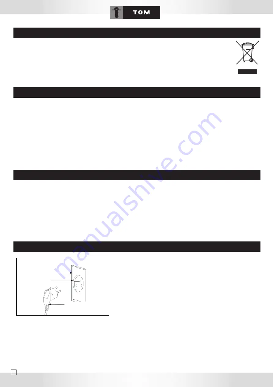
Earthing consists in connecting metal masses, that are liable to come accidentally 

in contact with the current due to faulty insulation in an electrical device, to an earth 

connection by means of a conductive wire. that earth connection, when used with 

a differential circuit breaker, prevents electrical incidents. The current flows directly 

into the earth and the power supply is automatically cut off. do not modify the sup-

plied plug. If it cannot be put into the socket, have an appropriate socket installed by 

a qualified electrician. If the earth conductor of a machine is incorrectly connected, 

this can lead to a risk of electric shock. the earth conductor is contained in green 

insulation with a yellow line. If the power cord needs to be repaired or replaced, do 

not connect the earth conductor to a live terminal. 

Call in a qualified electrician or maintenance personnel if the earthing instructions are not fully understood or if in any doubt about the 

correct earthing of the tool. If the power supply cable is damaged, it should be replaced by the manufacturer, the manufacturer’s after-

sales department or similarly qualified person in order to avoid any danger. Do not use a tool if its power cord is damaged. This tool is 

designed to be used with a circuit containing a power socket. It is also equipped with an earthing pin.

ENVIRONMENT PROTECTION

CONNECTING THE MACHINE – ELECTRICAL CONNECTIONS

NOISE INFORMATION

EARTHING INSTRUCTIONS

12

Outlet with earth

earth

connection

Summary of Contents for GTB10

Page 1: ...TOUR A BOIS ELECTRIQUE ELECTRICAL WOOD LATHE ELEKTRISCHE HOLZDREHBANK GTB10 Manuel d utilisation Operating instructions Bedienungsanleitung...

Page 2: ......

Page 3: ...st 33 TSR 210 parts list 33 TSR 210 motor parts list 36 TSR 210 stand parts list 38 conformity and warranty 43 deutsch allgemeine sicherheitsregeln 23 zus tzliche sicherheitsregeln f r tischkreiss gen...

Page 4: ...it de transporter les outils lectriques avec un doigt sur l interrupteur ou de les bran cher lorsque l interrupteur est en position marche peut engendrer des accidents d Enlevez les cl s de r glage av...

Page 5: ...SO 11203 1996 07 Les valeurs cit es sont des valeurs d mission calcul es selon les normes en vigueur et non des valeurs li es l utilisation sur le lieu de tra vail Bien qu il y ait une corr lation ent...

Page 6: ...r de blocage de la bride 4 glissi re du ban 13 bouton de blocage du porte outil 5 bride porte outil 14 interrupteur 6 porte outil 15 capot 7 contre pointe 16 levier de blocage de la poup e mobile 8 co...

Page 7: ...ciseau p n trer trop pronfond ment dans la pi ce pour viter tout risque d clatement ou de projection hors du tour Positionnez toujours le porte outil au dessous du centre de rotation pour les tournag...

Page 8: ...s assurant que la contre pointe p n tre au centre de la pi ce Bloquer la poup e mobile Tourner le volant pour fixer fermement la pi ce puis serrer le contre crou TOURNAGE EN UTILISANT LE PLATEAU TOUR...

Page 9: ...des eau d tergent etc Lubrifier r guli rement les pi ces mobiles pignons et axe Surveiller lors d un entretien que le lubrifiant ne vienne pas sur des parties lectriques les poulies ou la courroie Pro...

Page 10: ...210 stand parts list 38 conformity and warranty 43 deutsch allgemeine sicherheitsregeln 23 zus tzliche sicherheitsregeln f r tischkreiss gen 24 Symbole 25 installation 25 spezifikationen 25 montage 26...

Page 11: ...inger on the switch or connecting them with the switch set to on can lead to injuries d Remove any adjustment keys or wrenches before starting up the power If a key or wrench remains attached to a mov...

Page 12: ...ng to applicable standards and not values relating to use in the workplace Although correlation between those different emission levels does exist this cannot be reliably used to determine whether add...

Page 13: ...er 2 head stock 13 tool rest lock button 3 live centre 4 bed slide 5 tool rest clamp 14 switch 6 tool rest 15 cover 7 spur centre 16 tail stock lock lever 8 lock nut 17 face plate 9 tail stock 10 tail...

Page 14: ...allow the chisel to penetrate too deeply into the workpiece in order to avoid the risk of the workpiece breaking or being thrown out of the lathe Always keep the tool rest above the rotation centre fo...

Page 15: ...l the workpiece is clamped in place making sure that the spur centre goes into the centre of the workpiece Lock the tail stock Turn the wheel to secure the workpiece firmly and then tighten the lock n...

Page 16: ...dry cloth Never use liquids water detergent etc Regularly lubricate moving parts pinions and shaft During maintenance work make sure that lubricant is not applied to electrical parts pulleys or the b...

Page 17: ...rts list 36 TSR 210 stand parts list 38 conformity and warranty 43 deutsch allgemeine sicherheitsregeln 23 zus tzliche sicherheitsregeln f r tischkreiss gen 24 Symbole 25 installation 25 spezifikation...

Page 18: ...Tragen von Elektrowerkzeugen mit einem Finger auf dem Schalter oder das Anschlie en bei eingeschaltetem Ger t kann Unf lle verursachen d Vor dem Einschalten des Elektrowerkzeugs Einstellschl ssel abzi...

Page 19: ...elt es sich um gem den geltenden Normen berechnete Emissionspegel und nicht um mit der Verwendung der Maschine am Arbeitsplatz in Zusammenhang stehende Werte Zwar stehen Emissionspegel und L rmbelastu...

Page 20: ...ugauflagenhalterung 6 Werkzeugauflage 7 Reitstockspitze 8 Kontermutter 9 Reitstock 1 2 3 6 14 15 13 12 16 8 7 10 4 17 5 9 10 Handrad Reitstock 12 Spannhebel Werkzeugauflagenhalterung 13 Arretierung We...

Page 21: ...geboten 9 Den Mei el nicht zu tief in das Holzst ck eindringen lassen um jegliches Risiko des Zersplitterns oder des He rausschleuderns aus der Drehbank zu vermeiden Die Werkzeugauflage bei axialen D...

Page 22: ...rkst ck am anderen Ende durch Heranfahren des Reitstocks fixieren Dabei sicherstellen dass die Reitstockspitze in die Mitte des Werkst cks eindringt Den Reitstock sichern Das Handrad drehen um das Wer...

Page 23: ...igungsmittel etc verwenden Die beweglichen Teile Ritzel und Spindel regelm ig schmieren W hrend der Wartungsarbeiten darauf achten dass das Schmiermittel nicht mit elektrischen Teilen den Riemenscheib...

Page 24: ...en dehors de nos r parateurs agr s En aucun cas durant la p riode de garan tie le mat riel ne devra tre d mont 1 Scope of the warranty The warranty shall only apply to manufac turing defects or materi...

Reviews: