background image

Page 3

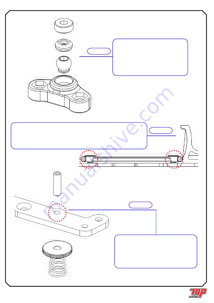
STEP 09,10 & 12の重要な注意点 / IMPORTANT NOTES FOR STEP 09, 10 & 12

注意: 

ピボットソケットインサートの位置付けに注意。

ピボットボールが、かろうじて回転するまでピボットソケッ

トネジをゆっくり  と締めてゆきます。ピボットボールがきつ

くなり始めたら、ピボットボール が再びかろうじて回転する

までピボットソケットネジを緩めます。

Note:

 Pay attention to the orientation of the pivot socket 

insert.  Tighten the pivot socket screw very slowly until 

the pivot ball is barely free to rotate. If the pivot ball starts 

to bind, untighten the pivot socket screw until the pivot 

ball becomes barely free to rotate again.

STEP 09 

から

from STEP 09

注意: 

リンクの位置付けに注意。リンクの両端にサイドスプリングが入る凹所があります。ピ

ボットボールがかろうじて回転 するまで両端箇所でM2x7 mmチェスヘッドネジをゆっくりと締めます。もしピ

ボットボールがきつくなり始めたら、 ピボットボールが再びかろうじて回転するまでネジを緩めます。

Note:

 Pay attention to the orientation of the link.  There is a recess area at both ends of the link for the 

side spring to fall into.  Tighten the M2 x 7mm chess head screw very slowly at both ends of the link until 

the pivot ball is barely free to rotate.  If the pivot ball starts to bind, untighten the screw until the pivot ball 

becomes barely free again.

STEP 10 

から

from STEP 10

STEP 12 

から

from STEP 12

注意: 

クロスブレースのカーボン材破損を避けるため、M3 

ネジ切りを使用し事前に2つ穴  (一つのみ示しています)を切り、

その後でイモネジに捩じ込みます。その際穴の深さは  半分にして

下さい。それでないと穴が緩くなり過ぎます。

Note:

 To avoid breakage of the carbon material of the cross 

brace, pre-tapp the 2 holes (ONLY one shown here) with an 

M3 tapper before screwing in the set screws.  Do it ONLY for 

half the depth of the holes: otherwise the holes will become 

too losse.

Summary of Contents for Rebel 12

Page 1: ...Page 1 Rebel 12 1 12 16 T O P Racing 16 1 2 3 4 5 6 7 300W ESC 1 12 540 64 4 8V 4 C 1 12 1 5 mm 2 0 mm 3 0 mm 5 5 mm 7 0 mm Rebel 12 Enjoy building and driving your Rebel 12...

Page 2: ...amage to property please be responsible when operating all remote controlled models ELECTRICAL PRECAUTIONS Insulate any exposed electrical wiring using heat shrink tubing or electrical tape to prevent...

Page 3: ...the link There is a recess area at both ends of the link for the side spring to fall into Tighten the M2 x 7mm chess head screw very slowly at both ends of the link until the pivot ball is barely fre...

Page 4: ...tention to the orientation of the suspension mount insert for each location as shown 2 Note Make 2x identical lower front suspension assemblies shown in the diagram on the left Ver 2 Front Suspension...

Page 5: ...PC RSU010 Front Suspension Ball x 2 PA SS0303BK M3 x 3mm M3 x 3mm Set Screw x 2 STEP 04 Front Suspension Ball M3 x 3mm M3 x 3mm Set Screw 0 5mm Upper Hinge Pin Clip 0 5mm 1 5mm Upper Hinge Pin Clip 1...

Page 6: ...in the above diagram Similarly make the left suspension assembly symmetrical to the right suspension assembly STEP 07 STEP 07 FINISHED Only Right Hand Side Shown Note The left and right suspension as...

Page 7: ...er O Ring 30 deg M3 x 8mm M3 x 8mm Countersunk Screw PC RMDS04 Link x 2 PC RSU011 Pivot Ball x 4 PA FN00M3 M3 M3 Nut x 2 PA SCM207BK M2 x 7 mm M2 x 7mm Chess Head Screw x 4 PA CM0306BK M3 x 6mm M3 x 6...

Page 8: ...M3 x 6mm M3 x 6mm Countersunk Screw M3 x 10mm M3 x 10mm Set Screw Ball Stud STEP 10 from STEP 10 2 M3 Note To avoid breakage of the carbon material pre tapp the 2 holes with an M3 tapper before screw...

Page 9: ...mm M2 5 x 6mm Countersunk Screw M2 5 x 6mm M2 5 x 6mm Countersunk Screw M2 5 x 6mm M2 5 x 6mm Countersunk Screw PC RCH011RD 8 75mm Ball Cup 8 75mm x 2 M3 x 8mm M3 x 8mm Set Screw x 2 Damper Tube x 2 P...

Page 10: ...ew x 1 45wt Note Use 45wt shock Oil sold separately Shock Shaft 1 5mm E 1 5mm E Clip Shock Piston Shock Body Shock Spring Adjuster O Shock O Ring Shock Guide Shock Guide Retainer Shock Cap Retainer Sh...

Page 11: ...8 1 4 x 3 8 Ball Bearing x 2 PA BM2508BK M2 5 x 8mm M2 5 x 8mm Button Head Screw x 4 REAR AXLE ASSEMBLY STEP 17 M3 x 8mm M3 x 8mm Countersunk Screw STEP 13 from STEP 13 STEP 14 from STEP 14 STEP 15 f...

Page 12: ...Ball 1 8 x 12 PA SB0168 1 4 x 3 8 1 4 x 3 8 Ball Bearing x 1 PA SB168F 1 4 x 3 8 1 4 x 3 8 Flanged Ball Bearing x 2 REAR DIFFERENTIAL STEP 19 STEP 17 from STEP 17 Rear Axle Left Hub 1mm 1mm Axle Spac...

Page 13: ...6mm M2 5 x 6mm Button Head Screw x 2 STEP 19 from STEP 19 Ball Stud M2 5 x 6mm M2 5 x 6mm Button Head Screw WARNING Cut the servo saver as shown in the figure on the left Be VERY CAREFUL doing it as...

Page 14: ...ntersunk Screw M3 x 8mm M3 x 8mm Countersunk Screw M3 x 6mm M3 x 6mm Button Head Screw Body Post Adjuster Body Post Adjuster Bumper Foam Body Post Roll Pin Body Post Roll Pin STEP 20 from STEP 20 PC P...

Page 15: ...r M3 M3 Lock Nut M3 x 8mm M3 x 8mm Countersunk Screw M3 x 8mm M3 x 8mm Countersunk Screw M2 5 x 6mm M2 5 x 6mm Button Head Screw 1 8 x 5 16 1 8 x 5 16 Ball Bearing E E Clip 1 0mm King Pin Shim 1 0mm S...

Page 16: ...Page 16 FINISH UP STEP 24 REBEL 12 REBEL 12 IS READY TO BE RUN ASSEMBLY NOTES...

Page 17: ...ETER 42 mm WHEEL Xceed ADDITIVE Paragon Ground Effect REAR TIRES TIRE Xceed Soft DIAMETER 44 mm WHEEL Xceed ADDITIVE Paragon Ground Effect NOTES BODY SHELLS MOTOR GEAR BATTERY ESC ESC SETTINGS STEERIN...

Page 18: ...SPRING SHOCK OIL FOAM INSERT NOTES FRONT TIRES TIRE DIAMETER mm WHEEL ADDITIVE REAR TIRES TIRE DIAMETER mm WHEEL ADDITIVE NOTES BODY SHELLS MOTOR GEAR BATTERY ESC ESC SETTINGS STEERING TRAVEL STEERING...

Page 19: ...Spacer 2mm PS PS06060 Rebel Side Spring 0 60mm x 6 coils 2pcs AW KS050RD Pan Car King Pin Spacer 0 5mm PS PS06560 Rebel Side Spring 0 65mm x 6 coils 2pcs AW KS100RD Pan Car King Pin Spacer 1mm Ball B...

Reviews: