Page 9
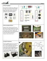
Electric Gear Controller Setup Continued.
•
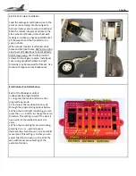
When the C and D lights are alternating,
pressing the + or
–
will increase or
decrease the servo throw on one end of its
movement. This setting is so that you can
adjust the door to open or close all of the
way without excessive binding at the
extents of motion.
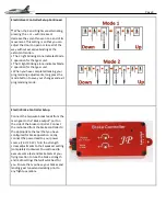
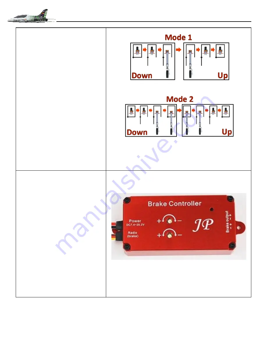
• The C light blinking alone indicates Mode
1 operation for that gear unit.
• The D light blinking alone indicates Mode
2 operation for that gear unit.
• When you have completed making your
programming adjustments, long press the
mode button to save your changes and exit
programming mode.
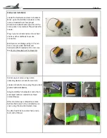
Electric Brake Controller Setup.
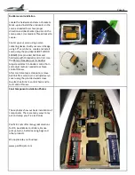
Connect the two-wire break leads from the
main gear to the “Brake output” port on
the side of the brake controller. Connect
the radio lead from the brake controller to
the appropriate channel that you have
configured for brake operation. Lastly,
connect the power lead to your power
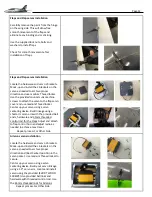
source (7.4V-25.2V). Turn the strength
screw adjustments to their weakest setting
(completely clockwise). You will need to
execute some taxi and brake tests at your
flying location to tune the brake strength
and radio settings that will work best for
you. Ensure that you have your brakes and
landing gear tuned and working prior to
any flight operations.


