Alarms
277
ID: um_tsmux
CP525 cMux User’s Manual Rev. 5.20.12 (3944)
Appendix C Alarms
The CP525 indicates alarm or failure status to the user in four ways:
•
WEB interface
•
Alarm LED on the front and on the rear
•
SNMP trap messages to Network Management System
•
Alarm relay
The user can define the severity level of the different alarm events. There are five levels, and
each level is also indicated by a colour on the alarm severity indicator:
Table C.1
Alarm severity levels
Severity
Level Colour
Notification
2
Blue
Warning
3
Yellow
Minor
4
Amber
Major
5
Orange
Critical
6
Red
In addition it is possible to set an alarm to filtered, so that there will be no alarm events
generated for this alarm.
The WEB interface gives the most detailed alarm information as all active alarms and warnings
are listed with time of occurrence
The unit sends an SNMP trap message to all registered trap receivers when an alarm condition
arises. A critical alarm will have severity level 6 and a Notification will have severity level 2.
When the alarm is cleared, a new message is sent to indicate that the alarm condition is cleared.
Finally, the red alarm LED will be lit when an unmasked critical alarm condition arises. At the
same time the alarm relay will be set to alarm state.
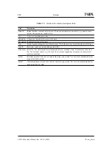
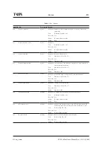
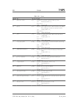
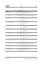
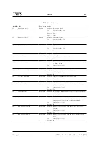
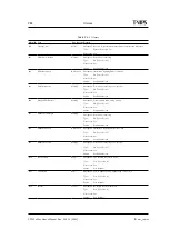
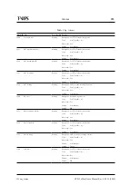
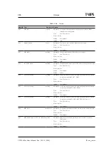
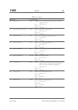
shows the possible alarms that can be signalled by the CP525. For each alarm type,
essential information is presented. The different fields are described in
.
Summary of Contents for CP525 cMux
Page 2: ......
Page 10: ......
Page 12: ...12 CP525 cMux User s Manual Rev 5 20 12 3944 ID um_tsmux ...
Page 18: ...18 CP525 cMux User s Manual Rev 5 20 12 3944 ID um_tsmux ...
Page 24: ...24 CP525 cMux User s Manual Rev 5 20 12 3944 ID um_tsmux ...
Page 66: ...66 CP525 cMux User s Manual Rev 5 20 12 3944 ID um_tsmux ...
Page 238: ...238 CP525 cMux User s Manual Rev 5 20 12 3944 ID um_tsmux ...
Page 248: ...248 CP525 cMux User s Manual Rev 5 20 12 3944 ID um_tsmux ...
Page 276: ...276 CP525 cMux User s Manual Rev 5 20 12 3944 ID um_tsmux ...

