Functional Description
51
ID: um_tsmux
CP525 cMux User’s Manual Rev. 5.20.12 (3944)
T
S
= 0.1s
2
1
0
2
1
0
2
1
0
2
1
0
2
1
2
1
0
2
1
2
1
0
T
B
T
A
2
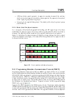
Sample point with down-count from flank to GPI state change
GPI signal
Filtered GPI state
Service switch position
T
A
0.2-0.3s Time from GPI flank to state change
T
B
Time from GPI state change to service switch
normal switch main to spare
normal switch spare to main
switch to spare, spare already active
interrupted switch
Switch spare to main, dual flank
T
C
T
C
More than 0.1s for successful flank detection
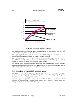
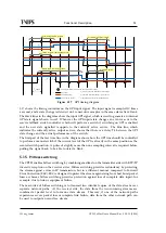
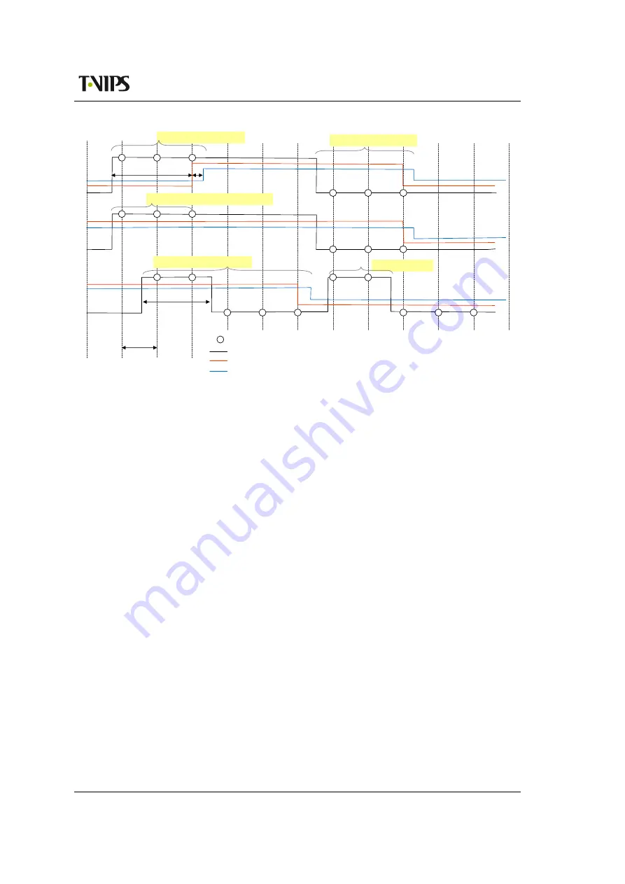
Figure 5.17
GPI timing diagram
shows the timing contraints on the GPI input signal. The input signal is sampled 10 times
a second, and a state change is detected on 3 consecutive samples in the same state after a flank.
The black lines in the diagrams show the input GPI signal, which is used to generate an internal
GPI state signal shown in red. Whenever the GPI input state changes an event is sent to the
service fallback switch controller, which will perform a switch if switching on GPI is enabled
and the new state signalled is oppsite to the currently active service. The blue line, which
indicates the currently active output service, shows that there is a delay T
B
between the GPI
state change and the actual performance of the switch.
The first part of the last time line in the diagram shows how the GPI line should be controlled
to perform a manual switch if the current level of the GPI is already in the same position as the
wanted switch position. A pulse of slightly more than one sampling interval is required before
pulling the signal back, to be able to detect a flank.
5.15 Hitless switching
The CP525 enables hitless switching by combining smallcast on the transmitter side with RTP/IP
diversity reception on the receiver sider. Hitless switching provides redundancy by protecting
the stream against errors in IP transmission, but in a different manner compared to Forward
Error Correction (FEC). FEC is designed to protect the stream against single or short burst packet
losses, whereas hitless switching provides protection against loss of complete data input, for
example, due to link or equipment failure.
The main idea of hitless switching is to transmit two identical copies of the data stream over
separate network paths. At the receiver side, the data from the two incoming streams are
combined at packet level to form one data stream. This way, if one of the network paths
experiences severe packet loss or complete link failure, data from the other network path can
be used to output an error free stream.
Summary of Contents for CP525 cMux
Page 2: ......
Page 10: ......
Page 12: ...12 CP525 cMux User s Manual Rev 5 20 12 3944 ID um_tsmux ...
Page 18: ...18 CP525 cMux User s Manual Rev 5 20 12 3944 ID um_tsmux ...
Page 24: ...24 CP525 cMux User s Manual Rev 5 20 12 3944 ID um_tsmux ...
Page 66: ...66 CP525 cMux User s Manual Rev 5 20 12 3944 ID um_tsmux ...
Page 238: ...238 CP525 cMux User s Manual Rev 5 20 12 3944 ID um_tsmux ...
Page 248: ...248 CP525 cMux User s Manual Rev 5 20 12 3944 ID um_tsmux ...
Page 276: ...276 CP525 cMux User s Manual Rev 5 20 12 3944 ID um_tsmux ...

