DHR/AR Series SALS Accessory Getting Started Guide
Page 11
In scattering theory, light is described by its angular wavenumber,
k
, defined as 2
π
/
λ
where
λ
is the wave-
length of the light in the scattering medium. Since
λ
=
λ
0
/
n
where
λ
0
is the wavelength of the light in a
vacuum, and n is the medium refractive index,
k
= 2
π
n
/
λ
0
. The dimensions of
k
are therefore (radians x)
inverse length.
The light wavevector, k, is defined as
k
times a unit vector in the direction of the light. Since the scattering
involved in SALS is almost completely elastic, the wavevector of the incident light,
k
i
, will have the same
magnitude as the scattered light,
k
s
, such that |
k
i
| = |
k
s
| =
k
.
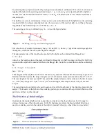
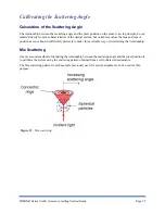
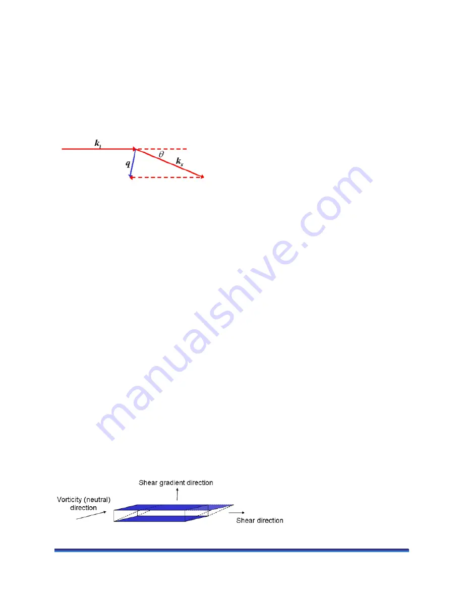
The scattering vector,
q
, is defined by
q
=
k
s
–
k
i
i
(see the figure below).
Figure 2
Scattering vector,
q
, and scattering angle,
θ
.
It can be shown by simple trigonometry that
q
= 4
π
sin(
θ
/2) /
λ
, where q = |
q
| and the scattering angle
θ
is
the angle by which the direction of the light has changed.
The approximate idea of the length scales probed by the light can be obtained from Bragg's law:
λ
= 2 L
sin
φ
where L is the length scale and the angle
φ
defined for Bragg's law is half the angle
φ
defined for SALS (by
convention the symbol
θ
is used rather than
φ
for Bragg's law, but in this context that would be confusing).
So:
L =
λ
/ 2
sin
φ
=
λ
/ 2
sin
(
θ
/2)
So L = 2
π
/
q
Thus the greater the length scale, the lower the value of
q
, and hence the smaller the scattering angle. In TA
Instruments SALS system, the range of angles over which measurements can be made is about 6° to 26.8°.
The wavelength of the laser used is 635 nm, and if the sample refractive index is taken to be that of water,
i.e., 1.332, the
q
range is 1.38 µm
-1
to 6.11 µm
-1
and the length scale range is about 1.03 µm to about
4.6 µm.
The scattering angle can therefore be used to gain an idea of the length scale of the structures present in the
sample. The intensity of the light and the scattering pattern give some idea of the spatial distributions of the
particles, and their number density.
The Direction of Incident Light
In principle, the incident light can be in any direction relative to the shear direction, but it is usual to
arrange it along one of the principle axes. In the TA Instruments system the shear gradient direction is
used, so scattering occurs in the plane of the vorticity (neutral) direction - shear direction (see below).
Figure 3
The three directions of a sheared sample.


