DHR/AR Series SALS Accessory Getting Started Guide
Page 14
Polarization
The diode laser used produces plane polarized light. In the TA Instruments system, the direction of polar-
ization is aligned with the shear direction. An analyzer (i.e., a second polarizer) is placed in the path of the
diffracted light. There are two positions for the analyzer, parallel or perpendicular to the direction of polar-
ization of the incident beam. The degree of polarization produced in the sample by shearing can be investi-
gated by comparing the scattering patterns produced with analyzer in the parallel and perpendicular
positions.
Intensity Adjustment
The intensity of the laser light itself cannot be adjusted, but the intensity of the incident light can be
reduced by placing a neutral density filter between the laser and the sample.
Intensity Corrections
Corrections to the intensity are only required for level 3 experiments (see
). The scattered light
falls on a flat sensor consisting of an array of pixels. The absolute intensity of the light,
I
abs
is obtained
from the intensity reported by the sensor,
I
sensor
through the relationship:
where bit is the bit depth of the chip. The sensor used has a gamma (
λ
) value of 1.0, so this correction is not
required.
However, a correction does need to be made for the fact that the flux of protons on each individual pixel
will depend on the angle at which it hits, and the distance of the pixel from the scattering center. It can be
shown that the correction for the angle is given by:
I
angcorr
=
I
abs
/ cos
θ
where
I
angcorr
is the intensity of the light corrected for the angle at which it hits.
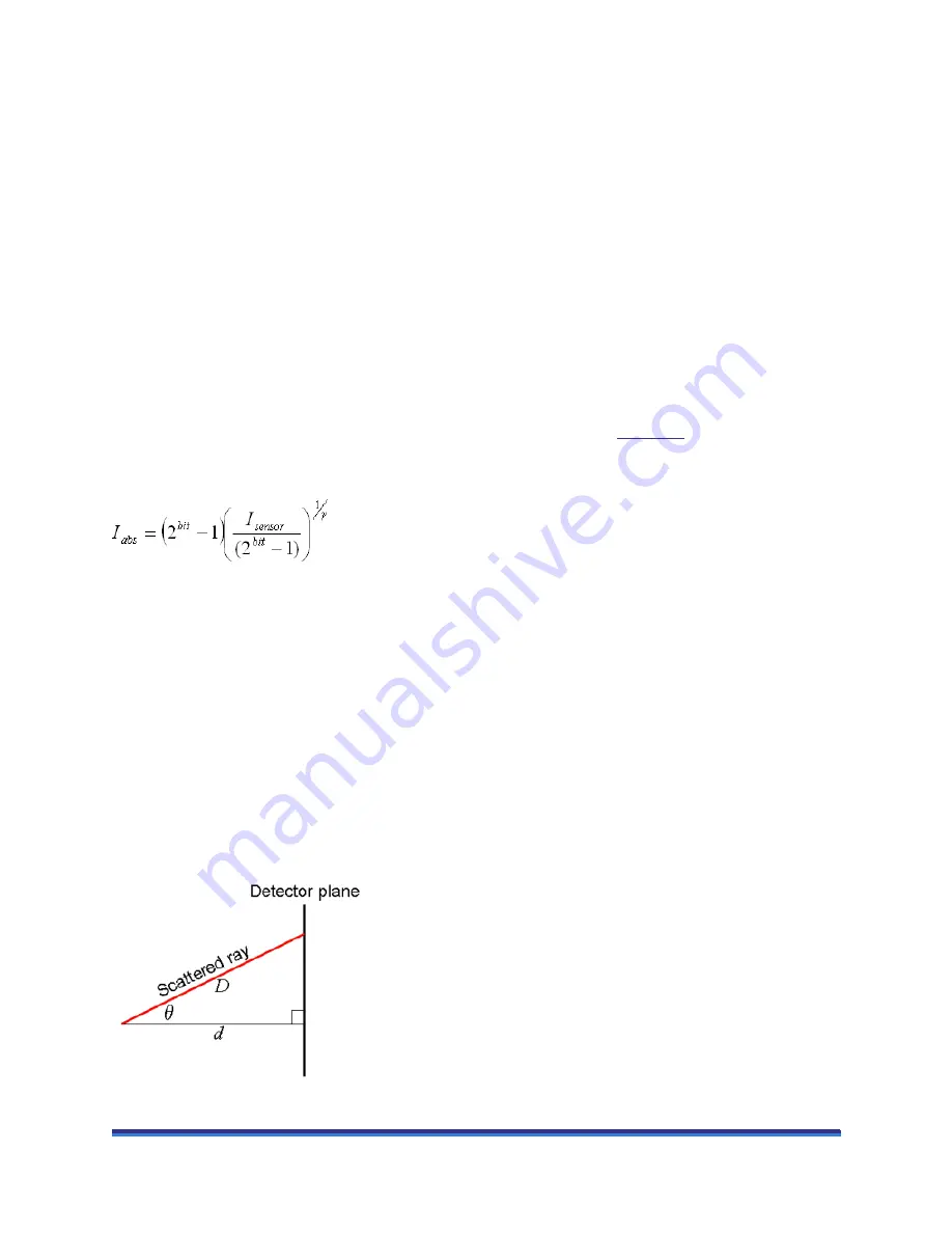
The flux of protons on a fixed area is also inversely proportional to the square of its distance,
D
, from the
light source, and since
D
2
=
d
2
/ cos
2
θ
, where
d
is the distance between the source and the plate in the
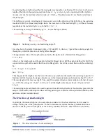
normal direction (Figure 7), the total corrected intensity,
I
corr
is given by:
I
corr
=
I
sensor
/ cos
3
θ
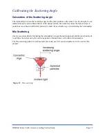
Figure 7
Paths for scattered (
D
) and unscattered (
d
) light.


