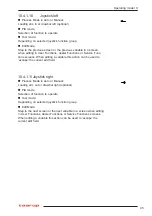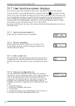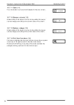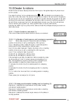
51
10.8 Dealer functions
Dealer function screens display parameters that may be changed/configured by dealer level
service people.
The dealer functions can be activated when the
&
combination are activated at the
same time in the Idle mode. The screens that appear are listed in the next section. Stepping to
the next screen can be accomplished by operating the joystick. Moving the joystick to the right
will step to the next screen, stepping to the previous screen is done by moving the joystick to
the left. When a parameter has to be changed/edited, activate any of the four edit switches:
clear (C switch), plus (joystick up), minus (joystick down) or equal (=/OK switch).
Pressing the STOP key in any step of this mode will finish the editing/monitoring and return to
Idle mode screen.
10.8.1 Dealer functions activated (1)
This screen shows that the dealer function screens are activated
10.8.2 Calibration of table sensor and emergency operation (2)
Parameter 1 indicates the angle between end position loading
and desired loading position.
Parameter 2 indicates the angle between end position unloading
and desired unloading position.
Parameter 3 indicates the allowed angle variance for the different
working positions.
Operating model C
Line 1:
End position forward: Forward the table to loading
position. Actual value is set by activating the -/OK key twice.
Line 2: Wrapping position. Adjust the table in horizontal position.
Actual value is set by activating the -/OK key twice.
Line 3: End position backward: Position the table in the un loading
position. Actual value is set by activating the -/OK key twice.
Line 4: Timer setting for table movement
Confirm T1 by activating the -/OK key twice.
Confirm T2 by activating the -/OK key once.
If the analogue senor fails, the table can still be operated by using
the timer setting T1 and T2. Actual values are depending on oil
flow, oil temperature and return pressure and it is therefore per-
haps necessary to adjust the values during a work shift.
T1 indicates the motion time from loading position to wrapping
position.
T2 indicates the motion time from wrapping position to unloading
position.
T1+T2 controls the movement from un-loading position to loading
position.
These values are normally set to 0,0 (zero).
10.8.3 Working position table loading and un-loading (3)
Summary of Contents for 7640
Page 2: ...2 Operator s manual round bale wrapper 7640...
Page 13: ...13...
Page 39: ...39 Operating model S...
Page 71: ...71 Notes 13 Notes...


