9100A/9200A/9400
2-2 Introduction and Operating Instructions
Four Channels
Each channel can output signals from -200 V to +200 V with
continuous currents up to 50 mA. The output has a fixed gain of
x50 and its output signal is driven from a 0.1
Ω
source impedance.
Normal loads are expected to be of resistive nature however, with
some degradation of its bandwidth, the output can drive capacitive
loads up to 1 nF, while maintaining its full amplitude range. Each
channel has a rear-panel monitor output that divides the main
output signal by 100. Having an output monitor is extremely useful
in such applications that require monitoring of the output signal with
low voltage sensors.
Modes of Operation
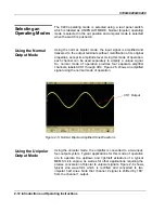
The amplifier can be used in one of two modes of operation. The
first is normal mode where each channel amplifies and outputs
bipolar signals. In this mode, the input signal is amplified and
delivered to the output terminals without modification of its original
properties, except its amplitude level. Using this mode of operation,
each channel can be used separately to amplify a unique signal.
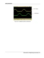
The second mode of operation is the unipolar mode where the
signal is applied to one input, rectified, amplified and output through
two separate outputs. Using this mode, the amplifier is converted to
a two-input, four-output system, specifically designed to operate the
up/down and right/left actuators of a typical MEMS micro engine, as
well as for other applications requiring the precise conversion of
bipolar to unipolar signals.
Safety
Safety played a major role during the design of the Model 9400.
The high voltage path to the amplifier circuit is blocked by a front
panel mechanical switch and accidental application of high power
to the UUT is prevented by a safety latch. The Model 9400 will
output high voltage signals only after the safety latch has been
lifted and the high voltage switch flipped to ON position. In
emergency situations, one can hit the protective latch to
immediately remove the high voltage power from the output
terminals. Also, red light glows on the front panel whenever the
high voltage is turned on. For added safety measures, the output
connectors are covered with protective caps to prevent accidental
touch of the inner pin of the output connector.


