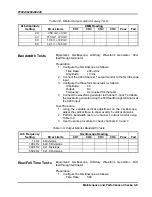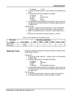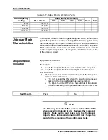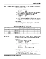
9100A/9200A/9400
2-12 Introduction and Operating Instructions
Selecting an
Operating Modes
The 9400 operating mode is selected using a rear panel switch,
which is labeled as UNIPOLAR MODE. Normal (bipolar) operating
mode is selected in the out position and unipolar mode is selected
when the switch is pushed in.
Using the Normal
Output Mode
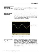
Using the normal, bipolar mode, the input signal is amplified and
delivered to the output terminals without modification of its original
properties, except its amplitude level. Using this mode of operation,
each channel can be used separately to amplify a unique signal.
So, normal mode of operation provides four separate amplifier
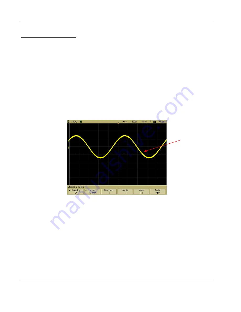
channels, labeled CH1 through CH4. Figure 2-5 shows an amplified
signal using the normal mode of operation.
CH1 Output
Figure
2-5, Normal, Bipolar Amplified Sine Waveform
Using the Unipolar
Output Mode
Using the unipolar mode, the amplifier is converted to a two-input,
four-output system. Typical applications for this mode of operation
are to operate the up/down and right/left actuators of a typical
MEMS micro engine, as well as for other applications requiring the
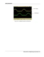
precise conversion of bipolar to unipolar signals. Figure 2-6 shows
typical sine waveform which is rectified and converted to two
unipolar half sines. Note that channel 2 signal is shifted by 180
°
from the channel 1 output.


