9100A/9200A/9400
Maintenance and Performance Checks 3-9
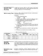
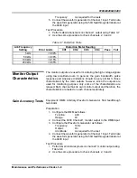
Table
3-8, Monitor Outputs Gain Accuracy Tests
Arb Amplitude
DMM Reading
Setting Error
Limits
CH1
CH2
CH3
CH4
Pass
Fail
2 V
350 mV,
±
3 mV
4 V
710 mV,
±
70 mV
6 V
1.06 V,
±
100 mV
8 V
1.41 V,
±
140 mV
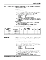
Bandwidth Tests
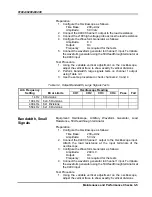
Equipment
:
Oscilloscope, Arbitrary Waveform Generator, 50
Ω
feedthrough terminator
Preparation:
1. Configure the Oscilloscope as follows:
Time Base:
200
μ
s/div
Amplitude: 1
V/div
2. Connect the 9400 Channel 1 output monitor to the Oscilloscope
input
3. Configure the Waveform Generator as follows:
Amplitude:
8 V
Output: On
Frequency:
As required for the tests
4. Connect the waveform generator to Channel 1 input. Terminate
the waveform generator using the 50
Ω
feedthrough terminator at
the 9400 input
Test Procedure
1. Using the variable vertical adjustment on the oscilloscope,
adjust the vertical trace to show exactly 6 vertical divisions
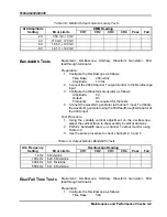
2. Perform bandwidth tests on channel 1 output monitor using
Table 3-9
3. Use the same procedure to check channels 2, 3 and 4
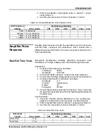
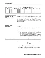
Table
3-9, Output Monitor Bandwidth Tests
Arb Frequency
Oscilloscope Reading
Setting Error
Limits
CH1
CH2
CH3
CH4
Pass
Fail
1 kHz
6 Divisions
100 kHz
6 ±0.5 Divisions
400 kHz
6 ±1 Divisions
550 kHz
6 ±1.8 Divisions
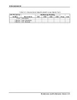
Rise/Fall Time Tests
Equipment
:
Oscilloscope, Arbitrary Waveform Generator, 50
Ω
feedthrough terminator
Preparation:
1. Configure the Oscilloscope as follows:
Time Base:
500

