9100A/9200A/9400
Maintenance and Performance Checks 3-17
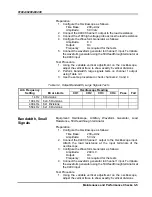
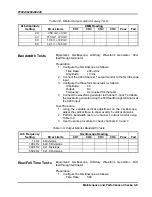
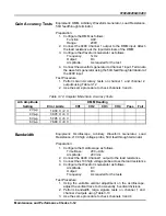
Bandwidth
Adjustment, Monitor
Outputs
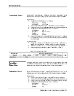
Equipment: Waveform Generator, Oscilloscope, x100 high voltage
probe, Load Resistance, 50
Ω
feedthrough terminator
Preparation (use the same procedure for channels 1 through 4):
1. Configure the oscilloscope as follows:
Time Base:
50 ns/div
Amplitude:
10 V initially, then use variable mode to
adjust to 6 vertical divisions
2. Connect the 9400 Channel 1 (then 2, 3 and 4) output to the load
resistance.
3. Connect the Channel 1 (then 2, 3 and 4) monitor output to the
oscilloscope
4. Configure the waveform generator as follows:
Waveform: Square
Frequency: 1
kHz
Amplitude: 8
V
5. Connect the waveform generator output to the 9400 Channel
1(then 2, 3 and 4) input. Use 50
Ω
feedthrough terminator at the
9400 input
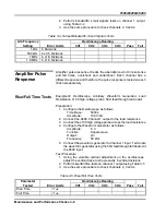
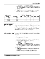
Adjustment:
1. Identify the trimmers for each channel and make the
adjustments below for rise time of 1
μ
s, ±100 ns
2. For channel 1, adjust RV5
3. For channel 2, adjust RV7
4. For channel 3, adjust RV9
5. For channel 4, adjust RV11
6. Modify the waveform generator frequency to 50 kHz and check
the adjustments. If results are not within the specified limits
alternate between 1 kHz and 50 kHz until adjustments until the
best result is achieved.
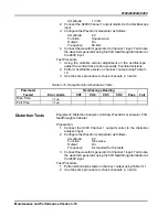
TIP
Always compare the pulse response from the monitor
outputs to the main outputs. Place the traces from both
outputs on the oscilloscope and, if necessary, re-touch the
adjustments (steps 2 through 5 above) until main and
monitor waveforms overlap as best as practical and
rise/fall times measurements fall within the specified limits.

