Appendix A
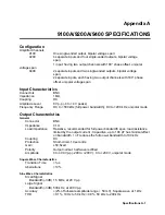
9100A/9200A/9400
SPECIFICATIONS
Configuration
Amplifier Channels
9100
One single-ended output, bipolar voltage span;
9200
4 separate inputs and four single-ended outputs, bipolar voltage
span;
1 input, having two output channels with 180
°
phase offset, unipolar
voltage span
9400
2 separate inputs and two single-ended outputs, bipolar voltage
span;
2 separate inputs, each having two output channels with 180
°
phase
offset, unipolar voltage span
Input Characteristics
Connectors BNC
Impedance 1M
Ω
Coupling DC
Amplitude Level
8 Vp-p (-4 to +4 V peaks)
Frequency Range
DC to >500 kHz (full power bandwidth); DC to >200 kHz, unipolar mode
Output Characteristics
General
Connector BNC
Impedance 0.1
Ω
Load impedance
Resistive, recommended for full power bandwidth spec, load resistance
limited by the output current ; Capacitive, up to 100 pF has minimal effect
on bandwidth, 1 nF reduces the full power bandwidth to 100 kHz
Coupling DC
Protection
Short-circuit, 10 seconds
Gain x50,
fixed
Polarity
Output normal; half wave rectified
Amplitude
0 to 400 Vp-p (-200 to +200 V); 0 to +200 V, unipolar mode
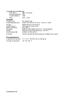
Square Wave Characteristics
Transition Time
<1
μ
s
Aberrations <10%
Sine Wave Characteristics
Small Signal
Bandwidth (-3dB) 1.5 MHz, at 20 Vp-p
Large Signal
Bandwidth (-3dB) 500 kHz, at 400 Vp-p
Accuracy
±
(2% of full-scale amplitude range + 50 mV), Square wave at 1 kHz
THD
<0.1%, 10 Hz to 50 kHz; <0.8%, 50 kHz to 200 kHz
Specifications A-1

