User Manual 9250
1-8 Portrayal
Figure
1-2, The 9250 Rear Panel
Line Receptacle and
Fuse
Power is connected to the 9250 through the line receptacle. The
amplifier accepts any voltage from 80 to 265Vac and there is no
need to select the voltage range between different countries.
Instructions how to connect the line cord and how to replace the
line fuse is given in Chapter 2. If a fuse blows, make sure you
replace it with the same type and rating to avoid possible damage
to the product from unsuitable fuse value.
Auxiliary Inputs
Channel 1
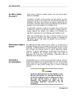
There are two Channel 1 auxiliary inputs on the rear panel marked
INPUT and OFFSET.
The INPUT connector can be used as summing input to the front
panel signal. It also can be used as the main input if connectors are
available on the back only. However, the output is always from the
front panel connectors. Observe the input limitations as specified in
Appendix A to avoid damage to the amplifier circuit.
The OFFSET connector is used for dc signals only. Use this input
to offset your signal to any direction, positive or negative however,
always observe the positive and negative rail limitations as
specified in Appendix A to avoid damaging the amplifier circuits.
With normal configuration, this input is used for driving the front
panel output for channel 1 only. When the 9250 is configured for
differential outputs, channel 2 auxiliary inputs are disabled and only
channel 1 signal is amplified.


