background image


Lucid-X Series RF Analog Signal 

Generator PXIe Module User Manual 

Rev. 1.0 


Confidential | 8  

Figures


Figure 1.1 LSX4091X 


 40 GHz, 1 channel, PXIe Module Microwave Signal Generator

 .................. 10


Figure 2.1 Lucid-X PXIe Module Rear

 ....................................................................................... 15


Figure 2.2 Front Panel

 .......................................................................................................... 16


Tables


Table 1.1 Ordering Information

 ................................................................................................ 9


Table 4.1 Frequency Specifications

 .......................................................................................... 29


Table 4.2 Frequency Reference Specifications

 ........................................................................... 29


Table 4.3 Amplitude Specifications

 .......................................................................................... 29


Table 4.4 Phase Noise and Harmonics Specifications

 ................................................................... 30


Table 4.5 Modulation Specifications

 ........................................................................................ 31


Table 4.6 Inputs Specifications

 ............................................................................................... 32


Table 4.7 Outputs Specifications

 ............................................................................................. 34


Table 4.8 Multi-Instrument Synchronization Specifications TBD

 .................................................... 34


Table 4.9 General Specification

 .............................................................................................. 34


Summary of Contents for Preliminary Lucid-X Series

Page 1: ...Lucid X Series RF Analog Signal Generator PXIe Module User Manual Preliminary Rev 1 0...

Page 2: ...kind and from any cause whatsoever arising out of or in any way connected with the manufacture sale handling repair maintenance replacement or use of said products Representations and warranties made...

Page 3: ...Revision Date Description Author 1 0 23 Oct 2023 Original preliminary release Release supporting Lucid Control Panel Ver 1 3 400 and TE Update Tool Ver 1 1 212 LS4091M SPI_SCPI Commands Rev 1 0 TESG...

Page 4: ...Digital to Analog Converter dBc dB carrier The power ratio of a signal to a carrier signal expressed in decibels dBm Decibel Milliwatts E g 0 dBm equals 1 0 mW DDC Digital Down Converter DHCP Dynamic...

Page 5: ...cally Controlled Oscillator ns Nanoseconds PC Personal Computer PCAP Projected Capacitive Touch Panel PCB Printed Circuit Board PCI Peripheral Component Interconnect PXI PCI eXtension for Instrumentat...

Page 6: ...erface SRAM Static Random Access Memory TFT Thin Film Transistor T M Test and Measurement TPS Test Program Sets UART Universal Asynchronous Receiver Transmitter USB Universal Serial Bus VCP Virtual CO...

Page 7: ...ing For Shipment 13 2 INTRODUCTION 14 2 1 UNPACKING 14 2 2 LUCID X PXIE MODULE REAR 15 2 3 LUCID X MODULE FRONT PANEL 16 2 4 MULTI INSTRUMENT SYNCHRONIZATION OPERATION TBD 17 3 TROUBLESHOOTING 18 3 1...

Page 8: ...nel 16 Tables Table 1 1 Ordering Information 9 Table 4 1 Frequency Specifications 29 Table 4 2 Frequency Reference Specifications 29 Table 4 3 Amplitude Specifications 29 Table 4 4 Phase Noise and Har...

Page 9: ...wing models listed in the ordering information Table 1 1 Ordering Information Model Description LSX8081X 8 GHz 1 channel PXIe module microwave signal generator LSX2091X 20 GHz 1 channel PXIe module mi...

Page 10: ...Signal Generator PXIe Module User Manual Rev 1 0 Confidential 10 Figure 1 1 LSX4091X 40 GHz 1 channel PXIe Module Microwave Signal Generator 1 2 Related Documentation Lucid Control Panel User Manual T...

Page 11: ...taborelec com downloads 1 4 Document Conventions Caution A Caution indicates instructions which if not followed may result in damage to the equipment or to the loss of data Note A Note provides additi...

Page 12: ...e all the ratings and markings on the product Search this manual for further rating information before connecting to it Do not apply potential that is higher than the maximum rating Do not operate in...

Page 13: ...is not available purchase replacement materials 2 Be sure the carton is well sealed with strong tape or metal straps 3 Mark the carton with the model and serial number If it is to be shipped show sen...

Page 14: ...nalog communication systems The Lucid Series is designed to meet today s most demanding requirements that is needed from the R D benches to the production lines The module shall be plugged into a stan...

Page 15: ...Lucid X Series RF Analog Signal Generator PXIe Module User Manual Rev 1 0 Confidential 15 2 2 Lucid X PXIe Module Rear Figure 2 1 Lucid X PXIe Module Rear...

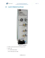
Page 16: ...l Generator PXIe Module User Manual Rev 1 0 Confidential 16 2 3 Lucid X Module Front Panel Figure 2 2 Front Panel RF OUT 2 4 mm type connector for RF signal output Status LED On RF OUT port is active...

Page 17: ...0 100MHz SMA type connector for 10 MHz or 100 MHz signal input FM SMP type connector for frequency modulation input CLK IN SMA type connector for 3 GHz signal input AM SMP type connector for amplitude...

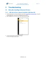
Page 18: ...USB Device Driver Manual Installation Windows 10 5 Download the latest Lucid series USB device driver from www taborelec com downloads Using the supplied USB cable connect the Lucid desktop model to...

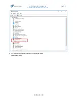
Page 19: ...Lucid X Series RF Analog Signal Generator PXIe Module User Manual Rev 1 0 Confidential 19 8 In the navigation tree expand Other devices and double click on CP2130 USB to SPI Bridge...

Page 20: ...Lucid X Series RF Analog Signal Generator PXIe Module User Manual Rev 1 0 Confidential 20 9 The CP2130 USB to SPI Bridge Properties window opens Click Update Driver...

Page 21: ...erator PXIe Module User Manual Rev 1 0 Confidential 21 10 In the Update Drivers CP2130 USB to SPI Bridge window select Browse my computer for driver software 11 Browse to the driver software location...

Page 22: ...Lucid X Series RF Analog Signal Generator PXIe Module User Manual Rev 1 0 Confidential 22 12 Driver download begins...

Page 23: ...ule User Manual Rev 1 0 Confidential 23 13 After the download is complete the driver installation begins 14 After the installation is complete the following success message is displayed 15 Click Close...

Page 24: ...X Series RF Analog Signal Generator PXIe Module User Manual Rev 1 0 Confidential 24 16 In the CP2130 USB to SPI Bridge Properties window the displayed device status should be The device is working pro...

Page 25: ...orelec com downloads 2 Connect the Lucid Generator to the PC using the supplied USB Cable The Installing Device Driver Software message is displayed at the lower right part of the screen 3 Wait for th...

Page 26: ...ick on CP2130 USB to SPI Bridge and select Update Driver Software from the drop list menu 9 In the Update Drivers CP2130 USB to SPI Bridge window select Browse my computer for driver software 10 Brows...

Page 27: ...Lucid X Series RF Analog Signal Generator PXIe Module User Manual Rev 1 0 Confidential 27 11 After the driver software installation is complete click Close...

Page 28: ...User Manual Rev 1 0 Confidential 28 12 In the Device Manager under Silicon Labs USB Devices click Silicon Labs CP2130 USB to SPI Bridge 13 In the CP2130 USB to SPI Bridge Properties window the device...

Page 29: ...z Resolution 0 001 Hz Phase Offset 0 01 deg Switching Speed Standard 500 s FS Option 100 s 4 2 Frequency Reference Table 4 2 Frequency Reference Specifications Frequency Reference Temperature Stabilit...

Page 30: ...cs Specifications Phase Noise dBc Hz Measured 10 kHz Offset 100 MHz 155 typ 250 MHz 147 typ 500 MHz 141 typ 1 GHz 134 typ 2 GHz 128 typ 4 GHz 123 typ 8 GHz 116 typ 10 GHz 115 typ 20 GHz 109 typ 40 GHz...

Page 31: ...Settable 100 Resolution 0 1 of depth Modulation Rate DC to 100 kHz Phase Modulation Peak Deviation 360 deg Modulation Rate DC to 100 kHz Pulse Modulation PLS Option On off Ratio 70dB Rise fall Time 1...

Page 32: ...igger Connector Type SMP Input Impedance 50 Input Voltage TTL CMOS compatible Threshold 1 5 V Damage Level 0 42 V or 5 42 V Reference Input Connector Type SMA Input Impedance 50 Waveform Sine or Squar...

Page 33: ...F Analog Signal Generator PXIe Module User Manual Rev 1 0 Confidential 33 Inputs Power 10 dBm Absolute Maximum Level 12 dBm AM Connector Type SMP Input Impedance 50 Maximum Input Voltage 1 V Input Dam...

Page 34: ...00 MHz Shape Sine Power 3 to 7 dBm Clock Output Connector Type SMA Input Impedance 50 Waveform Sine Frequency 2 7 GHz 3 0 GHz 3 3 GHz Power 10 dBm Absolute Maximum Level 12 dBm Multi Instrument Synchr...

Page 35: ...0 5 A max 12 V 5 5 A max Interface PXIe Gen3 x8 Lanes Dimensions WxHxD 8HP PXIe 2 Slots Weight Without Package 1 0 kg Shipping Weight 1 5 kg Temperature Operating 0 C to 40 C Storage 40 C to 70 C War...

Reviews: