background image

0-003-2060-1 (EN)

2 (6)

Designation

Explanation

Part number

M400

modulating control signal or increase/decrease signal

880-0230-020

M400-S2

modulating control signal or increase/decrease signal and end point
switches

880-0231-020

The actuator
The step motor of the actuator turns a
screw via a gear wheel. The motor
receives a control signal from a
controller. The screw gets a linear
movement which moves the stem of the
valve.

Control signal
M400 can either be controlled by an
increase/decrease signal or by a
variable direct voltage.

If an increase/decrease signal is used,
the actuator normally moves inwards on
an increase signal and outwards on a
decrease signal, see Settings.

Manual operation
There is a manual operation handle on
the actuator, see figure 2. When it is
lowered, the motor stops. Then, the
actuator can be operated manually if
the handle is turned.

Position feedback
Forta actuators are equipped with a 2–
10 V DC position feedback signal,
where 2 V always corresponds to the
closed position and 10 V to the open
position.

End point switches
When actuators are controlled in
sequence, it is possible to use the end
point switches that have set positions.
They will toggle when the valve is fully
open or fully closed, respectively.

Manual
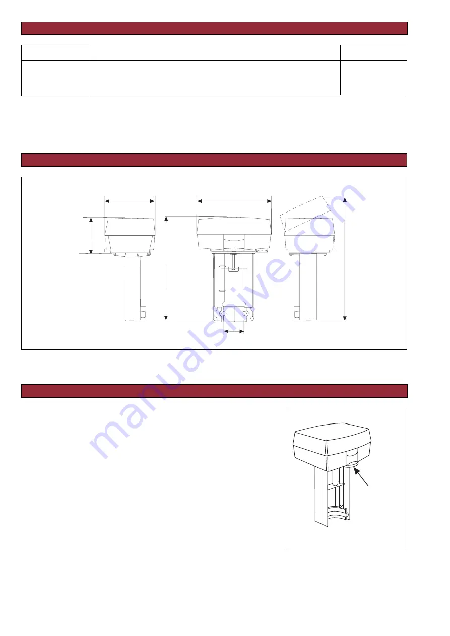
operation
handle

PART NUMBERS

FUNCTION

Figure 1

DIMENSIONS

173

44

315

82

242

117

(6.81)

(4.60)

(9.53)

(3.235)

(1.73)

(12.40)

Mått: mm
Dimensions: (in.)

Figure 2

Summary of Contents for Forta M400

Page 1: ... by 24 V AC It can provide 16 V DC voltage supply for older TAC controllers Actuator for Valves G 40 22 11 Jun 2003 TECHNICAL DATA M400 Part numbers see the table on the next page Supply voltage 24 V AC 10 50 60 Hz Power consumption average 6 VA Transformer sizing 30 VA Running time Modulating 60 s Increase decrease 300 s 60 s Stroke 10 32 mm 0 39 1 26 in Factory set stroke 20 mm 0 79 in Thrust 40...

Page 2: ...moves inwards on an increase signal and outwards on a decrease signal see Settings Manual operation There is a manual operation handle on the actuator see figure 2 When it is lowered the motor stops Then the actuator can be operated manually if the handle is turned Position feedback Forta actuators are equipped with a 2 10 V DC position feedback signal where 2 V always corresponds to the closed po...

Page 3: ...allations on the following conditions the cables between the controller and actuator are shorter than 100 m 328 ft the cross sectional area is larger than 1 5 mm2 AWG 16 and the cables are only connected to one actuator Please refer to the figures labelled Simplified installation for wiring instructions Cable lengths The cables to G G0 and G1 should be max 100 m 328 ft and have a cross sectional a...

Page 4: ...ta Controller Normal installation 4 wires to the actuator Short cable installation 3 wires to the actuator Forta Controller Forta Controller Normal installation 5 wires to the actuator Short cable installation 4 wires to the actuator Forta Controller Forta Controller Normal installation 5 wires to the actuator PU unit installation 4 wires to the actuator Control cabinet 0 V 24 V AC G0 G K1 K2 KC G...

Page 5: ...age range to use the upper one 6 10 V 5 10 V or the lower one 2 6 V 0 5 V If the switch is in the NORM position the higher voltage corresponds to 0 and the lower one to 100 To achieve the opposite function the switch should be put in its INV position Running time 60 s 300 s During increase decrease control you can choose between 60 s or 300 s running time During modulating control the running time...

Page 6: ...e valve and opens it fully The adjustment is finished by the actuator closing the valve again the electronic circuitry then adjusts the stroke and the running time to the valve The set values are stored in the EEPROM of the actuator so that they will remain after a loss of voltage When the end position adjustment is complete the actuator starts to control the valve according to the control signal ...

Reviews: