iWorx® HPU3
505-035, Effective: June 30, 2015
23
© 2015 Taco Electronic Solutions, Inc.
Hydronic Zone Interaction
To configure the controller to be part of a hydronic zone, associate the controller with a BZU3 from the BZU3 control-
ler's configuration screens. Refer to the BZU3 Application Guide for details on this procedure.
The HPU3 controller initiates network communication with the associated BZU3 Zone controller, which replies with the
following zone parameters to the HPU3. These zone parameters take precedence over the HPU3 calculated parame-
ters:
• Space Temperature
• Occupied Setpoint
• Unoccupied Setpoint
• HVAC mode
• Fan mode
• Occupied state
When the HPU3 is configured to be part of a hydronic zone, the Space humidity may be obtained from either a separate
RH sensor or an SLink thermostat; either of these are connected to the STAT input and configured from the Thermostat
configuration screen.
Automatic Configuration
The HPU3 and iWorx® Local Control Interface (LCI) use a self-configuring network management scheme requiring no
external tools, binding, or L
ON
W
ORKS
knowledge. The LCI recognizes and configures the HPU3 when the controller’s
service pin is pressed. The controller’s status light flashes green until the controller is configured, and is solid green
after the controller is configured. Once the service pin has been pressed, no further action is required by the user; the
controller is fully accessible to the LCI. Users may bind to SNVTs on the HPU3 with LNS or other L
ON
W
ORKS
tools if
they wish.
The LCI also provides network supervision of the HPU3. The LCI periodically sends a "ping" message to the HPU3,
which elicits a response. If the response fails, an alarm is displayed on the LCI. The LCI also uses the "ping" message
to refresh the occupancy mode and other system wide data.
Communication with Associated Controllers
In addition to Hydronic Zone interaction with the BZU3, the HPU3 is capapable of communicating with any LHP, GHP
and CCU controllers on the network to share demand and power usage data. These associations are configured from
the main controller screens of the other controllers.
Please refer to the iWorx®
LCI Application Guide
, iWorx®
GHP1 Application Guide
or iWorx®
LHP2 Application Guide
for a detailed description of how to associate the HPU3 and these other controllers.
CONTROLLER IDENTIFICATION
To register the controller with the LCI, press the service pin on the controller once it is properly installed and the LCI is
active on the network.
Once the HPU3 is properly installed and recognized by the LCI, the LCI can be used to configure the settings of the
controller. This section describes the commands available on the LCI for configuration of the HPU3, and the meanings
and default values for controller parameters. For more information on using the LCI, see the
iWorx® LCI Application
Guide.
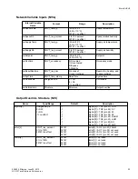
Network Inputs
The HPU3 allows a network manager to modify the Network Input Variables for the purpose of overriding configuration,
operation, inputs and outputs of the controller. Values written to the Network Input Variables have priority over normal
controller operation.

